What are the ways of connecting metal pipes? Coupling of Gebo coupling. Required welding equipment
July 25, 2016Specialization: finishing of facades, interior finishing, construction of dachas, garages. Experience lover-gardener and gardener. Also there is an experience of repair of cars and motorcycles. Hobbies: playing a guitar and a lot of other things that do not have enough time :)
The question of joining pipes without welding is always topical, since the welding machine is not available for every home master, and not everyone knows how to use it. At the same time, no pipeline is eternal, so this need may arise at the cottage, in a private house or in an apartment at any time. Below I will share with you some secrets of experts that allow you to perform such connections without welding.
Metal
First of all, it should be said that all existing pipes can be divided into two types:
- metal;
- plastic.
As a rule, the most problems arise with the docking of metal pipes, so first we'll look at the ways of their connection.
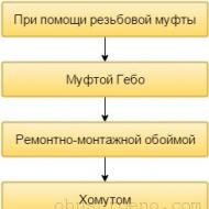
So, there are several options for airtight docking:
Below, we will take a closer look at each of these options.
With a threaded coupling
Most often, metal pipes without welding can be docked with a threaded connection. In this case, respectively, thread cutting is required. It should be noted that this is not such a complicated procedure, as many may seem at first glance.
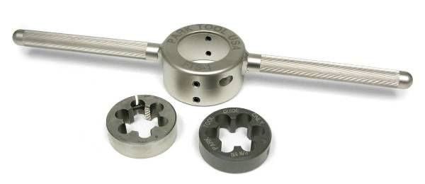
For tapping, you will need an electric thread cutter or dies to manually perform this operation. Since the price of the electric tool is very high, below I will tell you how to do the work manually:
- first of all, you need to clean the surface of the paint, which is subject to threading. If there are metal deposits on it, for example, those left after welding, they must be worn off;
- further, it is necessary to remove the outer chamfer from the end by means of a file;
- then on the prepared end of a detail it is necessary to put on a fork (plate) and to make a floor of a turn. In this case, it is necessary to make sure that the die is put strictly perpendicular to the axis;
- then you must perform a quarter turn back;
- by this principle the thread is cut to the required length. In the process of cutting, the cutters must be lubricated with a special liquid or any other lubricant;
- then, using the same scheme, the thread is threaded on another connected part of the pipeline.
For single-pipe coupling, the length of the thread must be several times longer than the other, so that it can be screwed onto the coupling with the nut.
After threading, it is possible to make a coupler connection by hand, which is performed as follows:
- a nut is screwed onto the long thread and then a coupling;
- a nut is wound on the second end of the part;
- then the pipes are connected, and the clutch is folded with the length of the thread, as a result of which it starts to be wound on the second part with a short thread. This procedure must be carried out until the junction point is approximately in the middle of the coupling;
- then nuts are twisted from both sides. Before they can be tightened, a coupling must be wound between the couplings and the nuts for waterproofing the joint.
This connection is reliable and durable. However, it is not always possible to thread. If, for example, the pipeline is located close to the wall, this operation is unlikely to be successful.
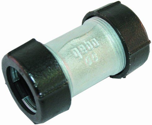
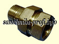
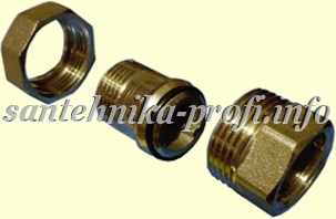
Coupling of Gebo coupling
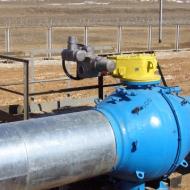
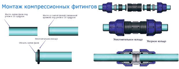
The Gebo coupling ("hebe" or "hebra") is a special compression fitting. With its help, it is possible to join steel pipes without threading and welding very quickly, without the need for any special tools.
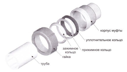
The scheme of its use is extremely simple:
- on the pipe parts are put on in such a sequence:
- nut;
- clamping ring;
- clamping ring;
- sealing ring;
- coupling;
- then it is necessary to put on the clutch to half and tighten the nut;
- then the second part is connected to the fitting in the same sequence.
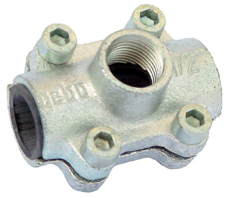
I must say that this fitting exists both in the form of a coupling, and in the form of a tee. This allows you to use it in those cases where you need to perform a sidebar, for example, in a riser for wiring.
As for reliability, this depends on the quality of the installation. If the work is done correctly, then this installation turns out to be reliable and durable.
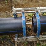
The connection of pipes without welding and threading can also be performed using a repair and mounting clip. This fitting is a coupling or tee, which consists of two parts. Both halves are pulled together by bolts.
It should be noted that the repair and installation clips are primarily designed for temporary repairs, for example, in the event of cracks. However, in emergency situations, they can also be used to connect the pipes, especially if the pipeline does not operate under high pressure.
In this case, the installation instructions are as follows:
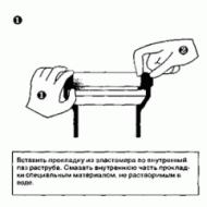
- first of all, the parts of the pipeline parts on which the fitting will be worn need to be cleaned of rust and all kinds of irregularities so that the outer surface is absolutely smooth;
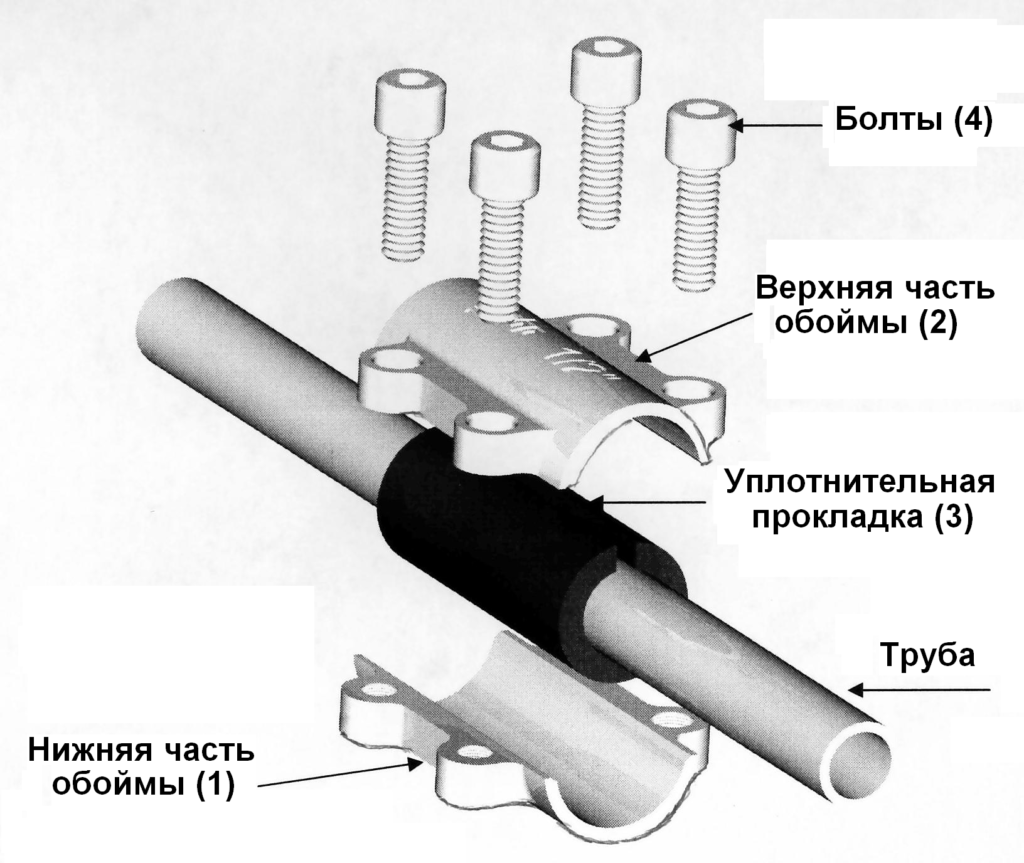
- then a rubber seal should be put on the pipe. The seal should be smeared with silicone sealant. It should be noted that the seal should completely cover the pipes so that there is no gap left.
- then both halves of the fitting are put on the rubber seal and tightened with bolts, as shown in the diagram.
This method, as we see, is also extremely simple. The same principle is used to connect the clamp-clutch. The only difference is that it is drawn from one side, not two.
I must say that if you use pipe clamps - the connection of pipes without welding is even more reliable than using an assembly and repair coupling.
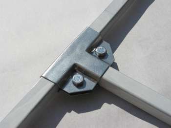
If you need to join the profile pipes without welding to build a structure, you can also use special profile clamps.
Plastic
If you need to assemble a plastic pipeline, you can use compression fittings that work on the same principle as the Gebo coupling. Most often in this way connect the metal and PVC pipes.
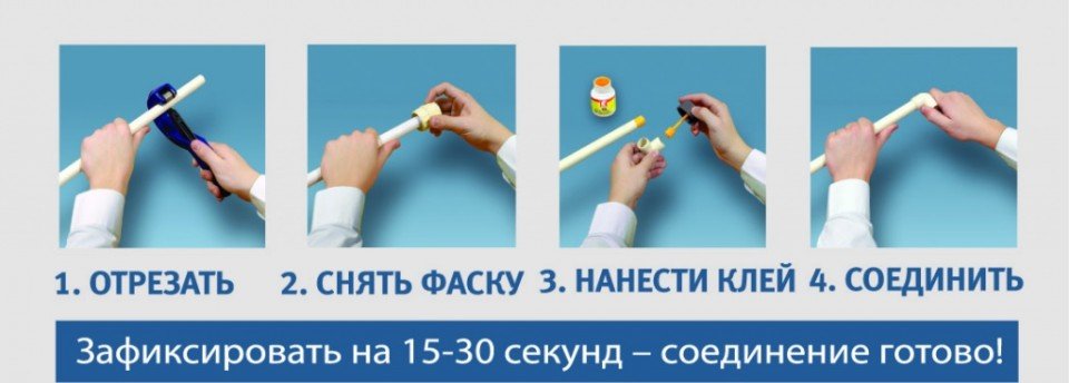
Also sometimes for these purposes use special glue. The installation process in this case is extremely simple:
- places are spread with special glue;
- then the parts are turned half a turn;
- in this position, they should be held until the glue cools.
I must say that this compound is quite strong, as the glue dissolves adjacent surfaces, and, in fact, welds them.
Also, for the assembly of metal-plastic pipelines, crimp fittings are also used. However, this requires a special tool that allows them to compress.
To perform temporary repairs, you can also use the clamps described above.
Here, perhaps, and all the most effective ways of joining pipes without welding, with which I wanted to acquaint you.
Conclusion
As we found out, in addition to welding, there are a number of other ways with which you can repair or even install a pipeline. And, some of them allow to receive not less reliable and durable connection. The only thing, in any case, the work must be done very carefully, in accordance with the recommendations above, so that the pipeline is sealed.
For more information, see the video in this article. If you have any difficulties in the process of joining pipes, ask questions in the comments, and I will definitely try to help you.
July 25, 2016g.If you want to express gratitude, add clarification or objection, something to ask the author - add a comment or say thank you!
The most widely used at present are prefabricated (sectional) radiators made of aluminum alloy.Their reliability can be very different - in the first place this is due to the design features of the product (usually the thickness of the radiator metal and the quality of the aluminum alloy).
* For example, if the store sells radiators from different manufacturers (one gives a guarantee for a year and at the same time indicates a service life of 15 years, and another guarantees 10 years with a service life of 50 years), even a person far from plumbing and heating equipment is unlikely there will be doubts which of these radiators is more reliable.
The price (with the same number of sections) can also be far from the same, but this is not the case when it should be saved.
* Relatively recently, the so-called "bimetallic" radiators appeared on the market (aluminum alloy from the outside, and inside the various sizes of the inserts of other metals, as a rule, steel).
The demand for such products (initially reaching a very high level) is now falling. Probably because (as life has shown) the benefits of such models are largely exaggerated. Of course, steel is a material much stronger than aluminum alloy. At the same time, its chemical resistance (in relation to the heat carrier) is also much higher.
However, all this can manifest itself only when tightness steel "shirt", that is, the absolute absence of contact of the coolant with the aluminum alloy.
Production of radiator sections such construction is expensive, part manufacturer is cunning, - steel pipes are installed only in separate sections of the section.
And if there is no contact of metals at the molecular level, there is always a possibility of leakage of the coolant between them.
And then it would be more correct to assume that water is not inside the steel pipe but a tube in the water.
In addition, direct contact in a common environment with the properties of the electrolyte of two different metals always leads to increased wear of less resistant (of course, the steel parts are in any aluminum radiator - futorki, plugs, plugs, nipple i, but the less of them, the always better).
Nothing but harm will not bring and various coefficients of thermal expansion of steel and aluminum alloy. Yes, and the heat transfer of such a radiator is reduced to some extent.
Of the quality radiators, we note the trademark "Nova Florida" (Italy), the company "Nova Florida" - the world's first manufacturer of sectional radiators made of aluminum alloy.
The declared service life is 50 years, warranty - 10 (for some models - fifteen).
* There are big doubts that on our heat networks the aluminum radiator can last for half a century, but for the quality of the coolant the radiator manufacturer does not bear responsibility.
 * When buying, also pay attention to the presence of factory defects and shipping damage (scratches, cracks, chips of the enamel), - the product should be unpacked completely when inspecting, and remove the protective film.
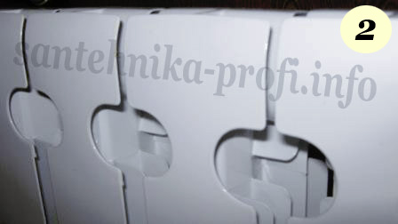
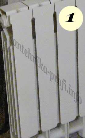
It would be superfluous to pay attention to some design features of the heater. For example, the gaps between the sections on the back (rear) side of the aluminum alloy radiators for the first time prevented the product from moving horizontally on the support hooks during installation (Fig. 1), and this greatly complicates the installation.
Currently, this moment is taken into account by almost all manufacturers (Fig. 2), but nevertheless the check does not hurt.
If the heater you need (in terms of the number of sections) is not on sale and there is no time to look for it, you can assemble the "battery" yourself, from two (or more) radiators eof the same size.
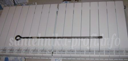
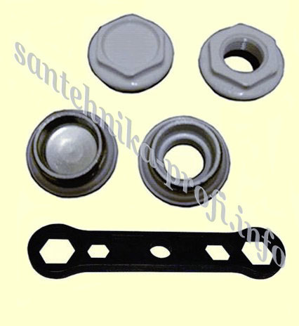
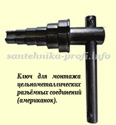
To assemble two radiators from one (or a section connection), you will need two radiator grids andspike, two inter-sectional gaskets and a radiator wrench.
Nippel i and gaskets (paronite or special cardboard) are sold in shops, the radiator wrench can be rented or manufactured independently (for the connection of one section, any handy tool, - the handle of the adjustable wrench, the strong chisel of the necessary width, the cutting of the steel strip s etc.).
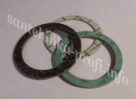
* Attention! Between the sections of the radiator should be installed only dense prefabricated gaskets designed specifically for this purpose.
Installation between the pads sections FROM RADIATOR FITTINGS, or SELF-DIFFERENT (from plain cardboard or rubber) IS NOT AVAILABLE!
Also keep in mind that it is recommended to increase aluminum radiators only with the same type of sections, and then almost certainly the docking points will be slightly different from the factory ones.
Build order:
Both radiators (either the radiator and the section) are placed on the flat flat surface on the back side (if you do not have a special stand with clamps for rigid fixing of the workpiece, it is much more convenient and reliable to collect on the floor than on the table).Two nipples mounted on the middle part (without threads) s) the gaskets are slightly screwed into the threaded outlets of one (b aboutof the radiator) to a minimum, only to not fall out.
* Do not mix up the polarity!
On the other hand, a nipple i slightly pressed by the joining section.
* Attention! No special preparation of the joints to be joined and the use of a sealant is not required.
At the same time, on the crimping planes of the sections (removed from the other radiator), the remains of the factory gasket may remain, which must be carefully crocheted e(without further grinding) with a construction knife with a thin blade.
Try the radiator wrench to the desired depth (the middle part of the tip of the "blade" of the key goes to the middle of the nipple).
* The process requires repeated extraction and rearrangement of the key for alternately tightening the upper and lower nipples.
You can try it on again every time, but you can simply mark the limit of the maximum depth (for example, using paper tape or an electrical tape applied to the axis of the key at the desired point).
Do not forget that in the process of screeding the depth of the key winding gradually decreases.
* The urgent advice of some "experts" to assemble and disassemble the radiator only two Keys (according to the principle of factory ties, to avoid skewing and damage to the product) should not be taken seriously. Such recommendations are usually given by people, either just beginning their activities in this area, or generally having nothing to do with it.
If the fitter is a fitter one radiator key can easily and simply do this job alone, then two keys will have to work a minimum of two, or even three (two twist, and a third locksmith holding a radiator). Benefits from such an organization of the order of assembly there is no - they will only interfere with each other.
As for the possible damage to the heater with an alternate tie, for the absolute majority of standard radiators (if elementary aforks) it is practically impossible.
 The fact is that the thread of the nipple (ø 1 inch) is very large, and the design (as a rule) provides significant gaps between it and the internal thread of the section.
And this, in turn, implies the inevitability of "backlash" in the joint with the screed.
In other words, the alternating twisting of each nipple on average by one revolution in the vast majority of cases can not lead to any dangerous loads.
Of course, until the last moment the key should be turned only by hand (without an additional tool) and only as long as the nipple "goes" completely freely.
Only after the alternately tightening of the nipples "by hand" (until the sections are fully joined), a final tightening is carried out using a lever that is inserted into the lug of the key.
This is done with a rather significant (but not excessive) effort in two stages alternately on each nipple.
Preliminary pulling of the nipples in the "pol.sily", the final - with almost the maximum force to which the average person is capable (with a lever length of 20 - 25cm from the key axis).
Once again we remind you, - you should stretch out fairly tightly but do not overdo it. Theoretically, both the cutting of the thread of the radiator section and the rupture of the nipple from excessive loading are possible (as a rule, this happens with excessive length of the lever).
A case was noted when the locksmith managed to break even the radiator key.
To hold the radiator (with significant loads on the key) should be as close to the connecting section as possible, on the side opposite to the direction of rotation.
* Attention! Our instructions regulate the order of "building up" sections of standard aluminum and bimetallic radiators. To build and build sections of non-standard radiators (for example, some bronze models with "fine" thread nipples), the above procedure is not fully applicable.
In the near future placement on the site of instructions for assembling non-standard models is not planned.
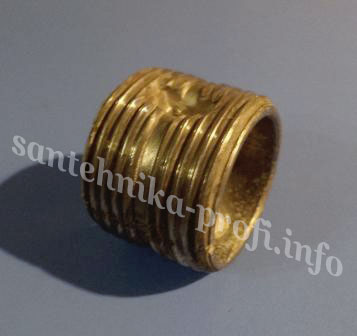
Now about radiator fittings
(end plugs - plugs and futorki with diameters of internal threads 1/2 or 3/4 inches).
Since radiators are assembled from separate sections by means of their clamping on nipples with external thread ø 1 inch of different directivity, the trunks and plugs (plugs) also differ in the direction of the external threads s.To your right (if you are looking at the front surface of the radiator), details are installed with the usual thread direction that we are familiar with s ("right"). On the left - on the contrary, only with the "left" thread.
* Diameter and pitch of external threads s radiator fitting completely corresponds to the sanitary standard (for ø 1 inch). Therefore, right to the radiator, if desired, you can screw in any sanitary connection with the external inch thread (stopper, transition connection to another diameter, steel pipe with threaded thread, threaded connection-transition to plastic, metal-plastic, copper pipe, etc.) without additional transition. . And here to the left such "focus" will not pass any more.
But there is a serious reason why this should not be done in any case - radiator fittings are designed for cushioning sealing, and a threaded plumbing winding.
Sealing the joint with any winding material implies a significant degree of its compression between the internal and external threads.
This is certainly a risk factor for the part with internal thread (in this case, the radiator section), and in fact aluminum alloy strength is much inferior to most other metals and their alloys used in plumbing.
If the section material is highly plastic, then such an "experiment" can end quite successfully. However, the aluminum alloy of radiator sections of most manufacturers is very fragile, and a direct winding connection can lead to the appearance of a longitudinal crack (across the threads) during assembly or some time after it. A depressurization of the existing heating system is a very dangerous accident, I'm involved with very serious consequences.
When choosing radiator fittings, attention should be paid to the thickness of the walls of the threaded part and the perimeter of the connection of the hexagonal part of the fitting with the thread.
* Important! Keep in mind that a serious manufacturer of radiators usually produces and everything that is necessary for their installation (in the first place, futurki and plugs) is also of very high quality. But! They almost never come bundled with the product (and this is correct, since the scheme of the installation can be very different and it is impossible to guess the optimal equipment). Therefore, if your radiator is still sold complete with futurks, plugs, fasteners, - keep in mind that this is almost certainly the initiative of not the manufacturer, but the supplier (and possibly the store) in order to get rid of the slow installation kits. At the same time they can be released anywhere (it is possible that they will not even be able to determine it).
On the radiator tubes and plugs-plugs of some not too economical manufacturers, there were cases of a crack at the base of the thread (up to the complete break-off) when installed on the radiator.
Pay attention also to the quality of the sealing gasket. A really reliable connection is provided by a gasket made of a durable material (eg dense rubber), deeply embedded (sometimes pasted) into the groove of the fitting crimp plane.
If this condition is not met by the manufacturer, then the probability of damage to the gasket during tightening or squeezing it out of the crimp plane (completely or partially) is very high.
 * By the way, the radiator fittings under the trademark "Nova Florida" (see above) are of exceptionally high quality.
* Before installing the futon on the radiator, the contact surface section grease special silicone sealant (not acidic).
* Radiator fittings (plugs and futorki) are usually produced in pure steel, painted with white enamel. When tightened (and tighten tight enough), any metal tool will damage the enamel and black marks will remain on the corners of the faces, which should be painted over after installation.
You can also use a special tool (not damaging the coating), for example plastic key for radiator fittings. The main condition that must be observed when working with such a tool is tight fitting it to the fitting at the moment of tightening. Otherwise, the plastic key will slide off under load and wear out to a greater or lesser extent, and after each "breakdown" the reliability of the subsequent fixing of the tool on the hexagonal part of the part will fall.
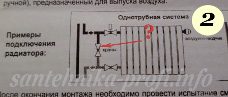
Such a system allows to regulate heat transfer your radiator, but does not create problems for your neighbors.
 Its scheme is extremely simple.
The upstream and downstream (upper and lower) radiator tubes are connected to each other by a pipe (bypass) on the tee, and an adjustment valve is mounted between the lower tee and the heating device (as usual, the normal ball valve of a reliable manufacturer works no worse).
One tap for adjusting the heat dissipation is enough, but it is better to install two (top and bottom). This will allow not disturbing the neighbors (and locksmiths of the service organization) at any time independently and completely disconnect the supply of coolant to the radiator (for example in the event of an accident, routine replacement or washing the device).
* IMPORTANT! One of the main operational rules of radiators based on aluminum alloys is the inadmissibility of a hermetic shutdown (ie shut-off valves at the inlet and outlet) of the filled radiator for a more or less significant period.
When aluminum and water come into contact, a chemical reaction occurs with the release of free hydrogen. This process in a closed volume in time, will inevitably lead to a critical increase in pressure and ultimately to an explosion.
Almost all manufacturers of aluminum radiators take into account such a probability (which is reflected in the design of the device), so most likely it will be a safe explosion. Perhaps even that you do not notice it, but the radiator (at least one of the sections) will become unprofitable uniquely.
If for some reason your "battery" has been disabled with both cranes, then open the first one should be carefully (smoothly) to avoid a water hammer (it is advisable to start from the lower one).
Involved in this system are mounted 3 cranes (installing the third on the bypass tube) to be able to direct the entire flow of coolant only through the radiator for maximum heat transfer).
 This is a serious violation, which can be compared to stealing someone else's property. After closing the "bypass" you take away imagine heat for which your neighbors paid money.
In addition, by accidentally closing one more (any) tap, you stop the circulation of the coolant throughout the riser. And this is not only administratively punishable and falls under a large fine, but it can lead to a serious accident (if part of the pipeline is in the freezing zone, for example, it goes to the attic of the building).
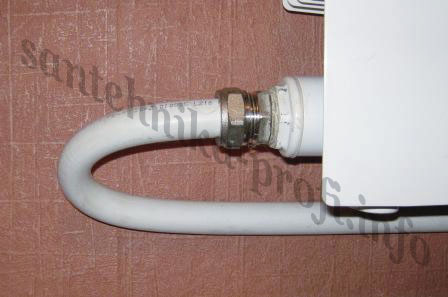
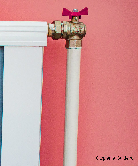
Even if such a connection scheme is indicated in the device's passport (see Photo-2), then (in any case, when connecting the radiator to the heating system of the apartment building) is not correct.
If you install a heater in your personal cottage, which is also heated by your personal "local" heating system, this is your personal business (although in this case the single-pipe connection scheme is ineffective and rarely used).
But the possibility of the tenant's interference in the adjustment of the overall heat distribution should be excluded!
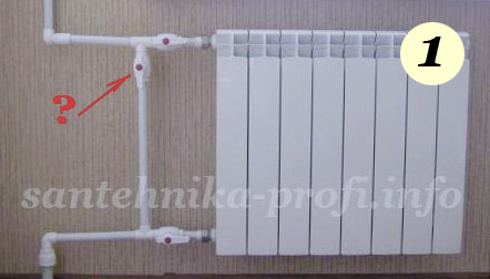
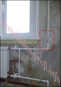
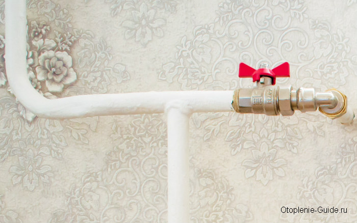
Now look carefully at photo # 1.
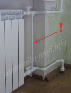
If you do not take into account the valve on the "bypass", then the radiator is otherwise mounted without any disturbances. And most importantly, a uniform inclination with a rise to the upper pipe is maintained.
At first glance it seems that the bias could be done less, but in this case it is not so. Top and bottom (from the neighbors) come steel pipes, which when the heat is applied (as a rule) are elongated from heating by several millimeters each. And if you set the slope to a minimum at installation, then after starting the system it may well become the reverse.
It is also very important to provide for these very horizontal pipe sections, at least 30 cm (between riser and bypass) to compensate for thermal expansion. If the pipes between the riser and the by-pass to aboutor they are not at all - all the load will go to the "bypass" and connecting elements.
And this not only spoils the appearance of the mounted system but also creates a real threat of depressurization.
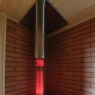
 Do not forget that when cutting old tools with electric tools, special attention should be given to the protection from the spark of window panes, window sills, decorative wall coverings, and fire safety measures.
Failure in the crack of the floor, or between the wall and the baseboard, a spark can cost you very much (especially in the presence of a fuel heater - in houses of Soviet construction it is very likely). At the same time to extinguish the beginning of the fire simply watering (without opening the floor) is very rare.
The finished assembly certainly looks much more aesthetic when the old pipes are cut out completely and the connection points are out of the boundaries of your room. If the neighbors are against, it is possible to thread the thread below the floor level with the cutout of the piece of board or drowning the pipe in the concrete base if there is a technical capability. The truth in this case, you may have problems when neighbors "ripen" to change their pipes up to your apartments.
So if you do not have confidence that this will happen only after many years, or there is no way to get them to pay for the additional work that will then have to be done you, then the point of joining the new pipe with the old one is best left outside.
The upper tube (in the similar case) before cutting it is desirable to cut to the maximum (2 - 3 cm from the ceiling).
* Of course, this is permissible only in cases where the pipe does not need additional fixation from possible rotation.
It is also advisable to check the degree of wear of old pipes (in the case of a significant one, - the thread may not bunk e(and in any case, too short a piece will not leave a chance for over-cutting in case of failure)).
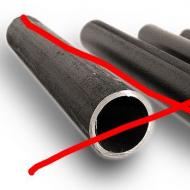
The installation of steel pipelines with the help of welding in the last century was sometimes performed by a pipe with an incompletely sanitary diameter (a little larger and with a smaller wall thickness).
Of course, you can weld anything, but it's very difficult to cut the THREAD on such a pipe (and in case of significant internal wear and tear aboutall is impossible).
Remove the "batteries" from the walls.
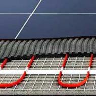
If you live in a panel house where the heating radiators (or rather the "coils") are keyed into the walls, the probability of their leakage with time is almost one hundred percent. And even if nothing of the kind has happened yet, the heat transfer at such a heating system always leaves much to be desired (especially since the inside panel heater eventually loses its properties and the house literally begins to "heat the street"). How to properly perform this work?
First, you may need permission, because we are talking about making changes to the design layout of building networks - here and there we are very strict with this, even if there is no other way out (especially when there is a real opportunity to untwist a tenant for a bribe).
Secondly, it is better not to connect the heating "snake" in the wall when attaching the external radiator (by the way, if you received an official permission to carry out such works, then this condition must be stipulated in it).
Well, thirdly, - if the internal "battery" is still stored, then try to install fasteners for a new radiator, it does not break.
Any standards when placing a steel "coil" in a panel wall at the time no one adhered. More precisely on paper they were, but in fact the pipe can be displaced by tens of centimeters in any direction and be drowned both very deeply and go to the surface of the wall (sometimes it can even be seen with the naked eye).
Here you can use a special device for positioning metal objects inside the walls, with which we can mark suspicious points when installing fasteners. In an extreme case, an ordinary small magnet suspended on a thread about 30 cm long (the sensitivity of such an "instrument" is generally sufficient for the task) is suitable. But in this case the inspection is greatly complicated by the presence of a large number of steel fittings inside the wall.
Drill the panel along the marked points should be very carefully, at low speed (the pipe in the wall is pierced by a puncher very easily).
Use only corner fasteners and short screws (the optimum length in this case is 16mm, drill and holes ø5mm).
And the best option is still forever forget about the "battery" in the wall and connect only the external radiator.
Connect the plastic pipe to the radiator with the help of non-removable threaded fittings (high-quality winding thread sealing is many times more reliable than crimping by rubber cushioning).
* Of course, in terms of ease of maintenance and possible repairs, a detachable connection is always more convenient. Typically, locksmiths - installers put detachable "American" for the release, in which a flat rubber (soft) gasket is crimped between the metal and plastic parts of the part.
Unfortunately, this connection is also the most unreliable.
Somewhat more reliable will be the part that is completed not with a flat, but round or cylindrical section with a gasket partially embedded in the metal part of the joint (possibly with sizing). However, in any case (especially the first time after installation), it is necessary to periodically check the tightness of the nuts on such connections.
The best in terms of reliability results showed the connectors on which dense the rubber gasket of the circular section is only crimped with metal (the gasket is installed in the annular groove and the crimping surfaces are not flat but of a conical shape).
A new pipe from the ceiling to the upper horizontal layer of the radiator should be attached to the wall in three to four points. If the same old vertical upper steel pipe is mostly preserved, then it is necessary to secure it securely to the wall with one detachable metal clip on the stud, at the lowest point.
Before installing the fixing hooks in the wall, it is necessary to make a marking, for which the new radiator is fitted as far as possible into the exact installation position.
* There may be many options for horizontal displacement relative to the window in the presence of free space. For example, in the center of the window or depending on the location of the furniture next to it. A good option is also the installation of a radiator under the opening flap, to create a thermal curtain in the path of cold air.
As for the heights installation, it (as a rule) is attached either to the height of the horizontal outlets (in case of their fixed position) or to the height of the window sill. For example, at a height of the opening from the floor to the bottom of the window sill 80cm, a standard radiator (50cm between the centers of threaded outlets) can be set both at the same distance between them and with some displacement down or up, there is no fundamental difference in this case.
Never install a heating radiator (water or electric) too high (when installing the unit on a wall without window this is possible) - this will lead to a sharp decrease in the efficiency of the "battery" and the loss of low and far areas from the heating zone.
Also (except for desperate situations), do not install the radiator too low (below 10cm from the floor level). This prevents the normal circulation of air, plus contributes to increased dusting of the heat sink fins sections.
Mark the installation position of the heater with a pencil on the wall, - the height of the upper plane, the center of the top thread, the marks of the intersection slots in which the fastening elements are planned to be installed (fasteners are required for the outer sections).
Measure the offset distance of the fixing point of the support hook (by trying to the radiator) down from the center of the upper threaded outlet (or from the top plane of the product) and apply the installation marks for the top row of fasteners to the wall, then mark the bottom row (using a tape measure and a plumb).
* Before hammering the top row of hooks, be sure to try them on a new radiator (on the side of the end section). On some radiator models, the bend of the heat sinks and the distance between them does not allow the use of such fasteners without further development. You may need to bend or trim and turn the hooks.
It should also be taken into account that even if the hook "fits" between the plates, this may not be enough. It must be possible to remove the radiator from it without changing its inclination, in a strictly vertical position (especially important for the upper row of fasteners).
Otherwise, the "battery" when hanging (or removing to adjust the fasteners) will be wedged between the upper and lower rows of hooks. And this will lead to damage to the enamel between the plates of the heat sinks and will greatly complicate the alignment of the product.
It is possible that the radiator without additional modification of fasteners in this case will not work at all.
First of all, two hooks of the upper row are installed at the extreme sections of the radiator (left and right). The basic adjustment adjustment (the exact height, the distance from the wall, the horizontality of the upper edge of the heater, the parallelism of the sill cut) is carried out on them. The upper intermediate hooks are drawn in one line along the cord between them, and only then the bottom row is set.
The distance between the upper and lower rows (at the points of contact with the radiator) may slightly differ from the interaxial distance, so when attaching the fasteners, you should adhere to a slightly smaller value (for a standard aluminum or bimetal radiator with an inter-axial distance of 50cm-50cm minus 2-3mm ), the error detected during fitting is eliminated by folding the supporting hooks of the lower row.
Only after checking the position of the heater with a plumb and horizontal level (as well as a complete absence of backlash in the reference points), the radiator can be considered completely fixed.
After connecting the pipelines, it is recommended to apply a thin layer of sanitary silicone (white or transparent) to the contact points of the support hooks with the radiator.
If you can not completely exclude the possibility of bias loads on the radiator during operation (for example in a children's room), then this may not be enough. It is necessary to close the device and all connections with a protective screen, in the extreme case simply perform additional fixing of the underside of the "battery" against the wall at several points with the help of mounting foam (until it hardens - only on a cold radiator!).
Now we will look at the ways of the most effective connection of the device during installation, i.e. without serious violations we achieve maximum heat transfer from the radiator.
Figure 1 shows a schematic diagram of a two-pipe heating system d aboutma with the top heat distribution (top filling), the connection of the radiators is lateral. And in Figure 2, the same system, but with a diagonal connection.
* Upper bottling means the planting of the main heat supply pipe to the very top (attic space or under the ceiling of the upper floor).
The common pipe through which the cooled coolant from the whole building returns to the boiler room ("return") passes through the basement or under the floor of the ground floor.
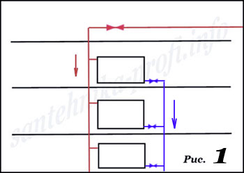
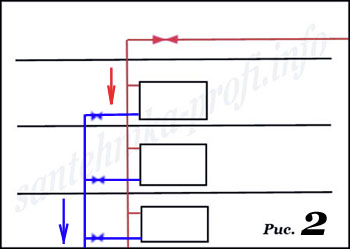
So, - on the scheme number 1, the heating devices are connected diagonally, and on the second - side.
And now the question is - at what connection is the "battery" going to heat better at the same temperature of the coolant?
We do not doubt that 100 people out of 100 will answer - at the first, diagonal, because it's obvious!
Is it so? Not really. Not everything here is so simple.
And the correct answer is this: at the recommended speed of the coolant in the system (by the way, very small), both schemes will provide almost exactly the same and very high heat transfer characteristics.
If the speed is too low (for example, the duct opening is narrowed), the heat transfer will decrease equally, if the circulation speed is much higher than the recommended one (for example, the circulating pump works in an autonomous system), the ratio may vary (but not necessarily in the direction of diagonal connection, rather vice versa).
Why is this, and why are the indicators in each case (at the optimum flow rate) high? The reason is simple.
Pay attention - in each figure the heat supply is connected to the upper pipe of the radiator and the branch pipe to the lower one, and this is very important.
Now more.
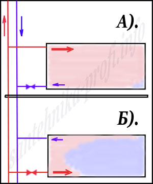
The figure shows two (absolutely identical, with the exception of the polarity) side connection schemes for a large sectional radiator (two-pipe heating system).
As you can see, in Figure A). The radiator warms up completely (to the extreme sections), practically over the entire area and its efficiency can reach 95%.
If the heating device is connected according to the scheme B), then the efficiency (for example, for a radiator of 12 sections) may not reach 40% (in fact, only the first 2 to 3 sections will be warmed up normally, and the effect of incrementing the additional ones will be close to zero) .
So why does the polarity of the connection lead to such completely different results? And there are two reasons.
First, when heated, the heat carrier (usually water) increases significantly in volume, so even a slight difference in temperature leads to a significant change in the weight of the same volume of liquid.
* By the way, it is for this reason that such a device hydro level (the "water" level, - two transparent vessels with divisions connected by a flexible tube) is more appropriately considered a teaching aid for physics lessons than a serious measuring instrument.
The slightest temperature difference between vertical sections of the hydro level leads to the fact that the device begins to lie ungodly (and the longer the length of vertical sections, the greater the error of the mark).
The second, - as already noted, the coolant in the central heating system moves with a small (even can be said - very low speed), despite the very high pressure (usually much greater than the pressure in the water mains). This is due to the fact that difference The pressure between the feed and the return is minimal (rarely more than 2x - 3%).
* Far from heat engineering people tend to consider the central heating system in some way a hybrid of hot water and sewage. Allegedly one pipe hot water is supplied under pressure and the other follows by gravity, and if the first one is blocked, then there is no need to block the second one and one can safely disassemble the pipes.
It is difficult to calculate exactly what percentage of serious accidents in the Russian housing stock account for this error. But that they are and they are not small, it is a fact.
When the coolant is supplied through lower the radiator tube hot water in a colder and dense medium immediately floats upward and practically all the same here goes further through the upper connection (Fig. A).
When submitting from above, light hot water "spreads" along the heavier cold layer on the entire length of the heating device, and as it arrives, it is evenly forced out into its lower part, cooling down.
We believe, the essence is clear - to achieve maximum heat transfer, the coolant must be supplied to the top of the "battery".
Unfortunately in our city apartments the most common one-pipe heating system, bottom bottling. No, of course from the basement aboutmA heating pipes go upward in pairs (feed and return), but the radiators are connected to both. Those. vertical pipe (riser) filing The coolant rises from the basement to the top floor of the building, feeding on each floor one heating device.
At the top, the feed riser moves to "reverse" on which the partially cooled coolant is lowered again to the basement, along the way feeding the neighboring row of radiators, each of which is usually already in another room, or even in another apartment. The temperature of the last "battery" in such a chain is involved in close to the temperature of the air in the room.
In the Soviet era, when no one saved fuel and did not touch the batteries in the apartment, the drawbacks of this connection were not very noticeable. Moreover, the adjustment fittings on radiators and bypasses were still in working order (however bad the Soviet JEC was with the lazy and insolent drunkards - locksmiths, but still "unlike most modern management companies" with their work "even on grade "but he managed).
In our time, the work of the heating system with such a connection tenants are usually unhappy always.
Firstly, a nedotopom now no one is surprised (here and there it is already considered the norm).
Secondly, serious control over the elements of the public house heating system, there is practically nowhere in the tenants' apartments. Everywhere the inviolability of the home and private property - the owners and tenants arbitrarily "rationalize" the scheme of connecting their radiators.
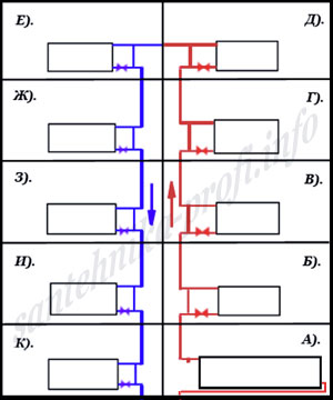 Let's give an example of such "rationalization" in one apartment for a one-pipe heating system of a five-story building.
During periods of nedotop, the owner of the apartment (A) notices that the living conditions have become much cooler than before, and the radiator normally only warms up its first sections.
And now he cuts the "bypass", increases additional sections and changes the connection scheme to a diagonal one.
As a result, it again is hot and always open the window.
* By the way, service organizations, heat network controllers and neighbors should pay attention to this. As a rule, the need for constant additional ventilation day and night is a sure sign of a violation by the tenant of the heat distribution scheme.
The share of the remaining nine apartments (B - K) is much less heat than now consumed by one apartment (A).
In principle, it is quite possible to adjust and adjust the operation of any heating system (for example, by shaking).
But such adjustment should be carried out only by the specialists of the service organization with the subsequent sealing of tuning units which excludes the interference of tenants in the general part of the system (up to the stop valves at the radiator inlet).
And further it is completely indifferent how he connects his radiator (from above, from below, from the side or diagonally), it is absolutely not important whether this is a five-section radiator or it will increase it to fifty sections, nothing terrible will happen in case of poor connection with a narrowing of the duct.
Any deviation from the design, recommended or optimal connection can only damage the very tenant - the "rationalizer" and in the heat supply of the neighbors, this will not be affected in any way.
Suppose you live in an apartment building on the top floor with a one-pipe heating system, where the operation of the common property is strictly (in our time it is usually HOA). If your radiator is the last one in the "feed" chain, then the next one after it (on the "return" - from the neighbors) will give out much more heat than yours (precisely because the coolant approaches it the upper branch pipe).
How to be in that case, - to arrange "overlap" with the air vent - automatic?
In no case. Such an assembly in the open version looks (to put it mildly) somewhat strange, but even if the pipes are sewn into the wall - this can create problems for the service organization when commissioning the system.
In addition, the advisability of using an air valve on the radiators is in most cases questionable.
Of course, it's very good when some device takes care of ourselves and we can not think about it anymore. But let's start from real conditions. And the reality is that most of these mechanisms do not differ in their compact size and high reliability.
The installation of a standard automatic air vent is unlikely to improve the appearance of the radiator as a whole, rather the opposite (especially since the absolute majority of such "automatic machines" more or less work reliably only in an upright position). In addition, it (as a rule) is much in favor of the "dimensions" of the device and can be accidentally damaged.
Automatic air vent valves are very sensitive to the contamination of the coolant, - a grain of sand or mote that has fallen into the valve can lead to a permanent leak, and this is despite the presence of a protective mesh (if it is provided for in the design).
To what (in due course) the contamination of such a grid can lead, is clear without explanation. Of course, this problem can be solved by installing an additional filter, but the appearance of this design will be even worse.
* Air vent - automatic (with a reliable filter) it is desirable to install at the highest point of the heating systems of buildings in the presence of a technical floor.
Very many manufacturers of aluminum radiators recommend its installation on each heater. In case you forget that it is unacceptable to hermetically close - the gas that was released was where to go.
* It is for this reason that it is forbidden to bring an open fire to the installed air vent. Possible consequences can be much more serious than a break from the gas pressure.
Such recommendations (just in case) are similar to advice to change the rug behind the threshold on a foam mattress (because if you accidentally stumble - it will be softer). In addition, the air outlet installation point is not actually the highest point of the radiator. Therefore, its protective functions in this case are very doubtful (at 100% coverage). And the radiator that has worked for a while in the heating system is always 100% full, even if it was not the case initially (any free gas is quickly absorbed by the flowing coolant).
The adjusting adjustment of the automatic air vent is rarely of a protected type (although a screwdriver) - as a rule it is a cap that is unscrewed (and twisted) very easily. Even a child can do it (after such an "adjustment" the air vent will most likely stop working in the automatic mode, and more serious consequences are possible).
Therefore, we prefer not to place such air ducts on apartment radiators in general (except in some cases when the "battery" is the top point of the system and is completely hidden behind the protective screen).
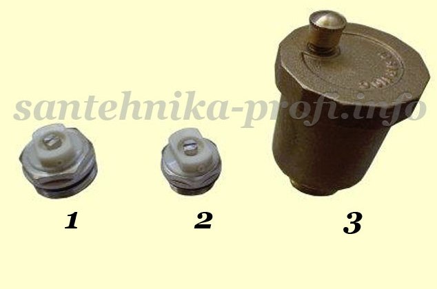
On open-type radiators, it is better to install simple small-size air outlets (air is discharged through them using a conventional flat screwdriver or a special key).
1). Small air vent (ø 3/4 inch).
2). Small air vent (½ "thread).
3). The air vent is an automatic (1/2 inch thread).
 On the heating devices that are in the upper points of the system - the installation of the air vent is mandatory (it should be borne in mind that if the slope of the pipelines on the floors is not executed correctly, then from any standard air vent when starting the use will be small - instead it is better to install a conventional ball valve reliable manufacturer).
If the pipes go higher (through the overlap) to the neighbors or to the technical floor, - at your discretion. There is no special need to install the "air vent" (it can be useful to you only to check the condition of the heating system, ie the presence of pressure of the coolant).
Sometimes the possibility of such a check can be very useful.
Take, for example, this case: on the third floor of a typical five-story building, the shabashniki replaced the two old radiators with aluminum ones, and the connection was made with a plastic pipe ø20mm with the maximum possible bend with the help of an internal spring.
 The bending point is rigidly fixed, so after some time, cross-section cracks of the outer layer of metal-plastic (if left as it is, before the accident is near) went.
This time the owner invites our specialists and orders a paid trip in the service organization. And since the master plot is located in this same building, everything passes operatively, the master reports that everything is off - you can work safely.
Our mechanic begins to replace the pipelines of the first radiator, - having previously opened the air vent to check the shutdown state. It's all right, there's no pressure.
Having finished this work it moves to the next radiator, - the air vent on it is NOT INSTALLED.
The radiator is cold (but the heating season has just ended, so this is not an indicator), so the locksmith informs the owner that there is no possibility to check the condition of the shutdown and dismantling in case of anything is under his responsibility. The owner gives good without the slightest doubt, motivating that the master of the service organization has guaranteed a normal trip.
Locksmith begins to disassemble, between the case explaining to the owner that the shutdown guarantee and the shutdown itself is not the same thing. What a locksmith i the management company could forget to turn it off, but could turn it off - but not that.
In general, he explains all this and he quietly turns, because the first radiator was really switched off, there are no leaks when disassembling (and responsibility is not on it - you can relax a little). He does not have time to unscrew the connection to the end, as he is knocked out by pressure and we have a serious accident. Of course, it was quickly eliminated and neighbors from the bottom did not suffer (but recently made repairs, new furniture and the computer's system unit water drove decently).
Called the site master, explained the situation, agreed on a meeting (the benefit of going close).
He comes, and brings a suspension aboutto with a sawn-off handle. Say, someone from the tenants cut down the deputy aboutto and started heating - so the accident, and the management company has nothing to do with it.
What kind of unauthorized launch can be, because all radiators are cold? But just try to prove now that the cause of the accident is the mistake of locksmiths in the service organization (as well as the fact that the deputy aboutto the basement room in all likelihood is just what they sawed in the workshop ...).
Now about why in this case until the last moment there was no leakage at disassembly (in spite of the total pressure in the system).
And the reason is simple a, - sealing winding itself is always "dangling" on the external thread, but here at disassembly zachechyu remains on the inside.
It is for this reason, leakage (even drip) may not be observed until the last second.
* Do not apply significant force when installing a small air vent on the radiator (possibly internal damage, - for any suspicion of this possibility, the part should be replaced!).
After venting the air, close the screw carefully (until the leak stops and a light additional clamp for reliable fixing, - never tighten the screw "to the stop"!).
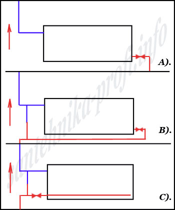 So, how can we "force" the radiator to warm up completely, to the extreme sections. A good option for heating systems with a lower (problematic) supply of a coolant is a diagonal connection (Fig. A). However, more or less decently this system looks only if the supply and discharge coolant pipes are on the opposite sides of the "battery" and "bypass" project is not provided.
And if not? After all, in our apartments, the pipes usually pass from one side.
Usually in such cases for the diagonal feeding of the instrument the lower pipe is allowed under the radiator (Figure B), which certainly clutters the construction and in some cases simply impossible.
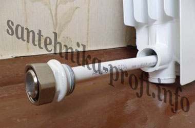
But there is another, much more aesthetic way of such installation, this is (Fig. C) an internal diagonal connection.
As shown in the figure, from the inlet threads s through the bottom of the radiator (through the radiator nipples i) is a metal-plastic tube ø16mm (tube ø20mm usually does not pass and even a partial flattening of pipes s does not help, since the nipple i on the joints of sections are rotated under the most different angles).
* In order to maintain the normal flow of coolant inside the m / n tube, it is not permissible to insert anything.
In the diagram for clarity, it is shown that the end of the tube does not reach the far point of the radiator a little (the coolant passage is left).
In fact, the metal-plastic pipe should go to the very end and slightly abut the plug.
Normal flow provides special preparation of the pipe ends at the inlet and outlet.
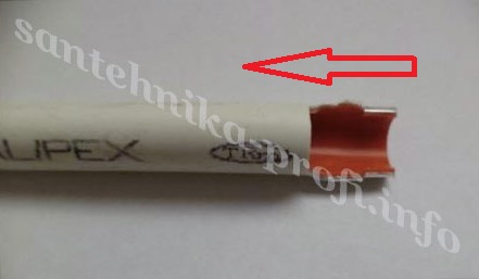
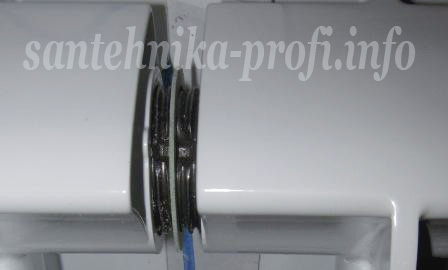
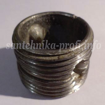
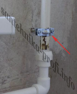
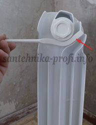
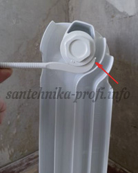
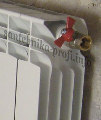
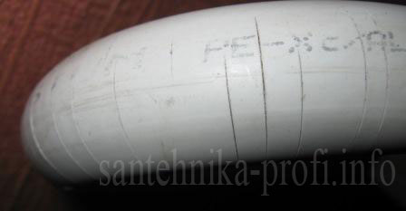
 * On the input side is cut (for example, with scissors for plastic) half the diameter of the pipe for the required length and cut at the desired point with a turn - to limit the depth of installation (after the tip is inserted inside the connector before the stop, the cutout should protrude about 5 mm behind the extreme point of threading the futurki, - see the photo).
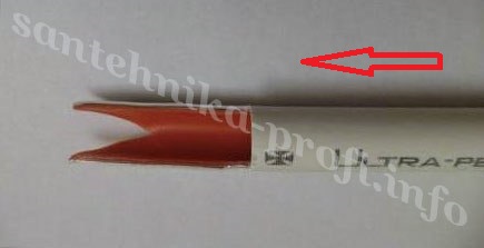
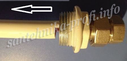
At the outlet of the pipes s also cut half the diameter (for a length of about 5 cm), while its tip should be shaped like a "swallowtail" (see photo).
On the fully assembled radiator, both cutouts must be directed downward.
Heat transfer in this connection is practically the same as the "classical" diagonal (in this case, such a "modernization" of the radiator is completely invisible).
Do not forget also that even excellent heat transfer characteristics of heating devices can negate the high heat losses of the room.
In the face of the possibility of underdogging, it is very important that modern windows and doors (preferably double) are installed in the apartment. A very good option would also be additional insulation of the "street" walls. This device is a false wall with a heater (preferably foam or other similar material).
* Warmth of min.wat only with additional vapor barrier! Without hermetic packing of briquettes it is allowed to lay it only in internal partitions - for soundproofing, otherwise on the boundary of a cold wall and a warm room it will quickly dew.
The construction of a false wall around the window opening also allows you to hide defects capital walls (and as we know, there is no ideal quality of walls in our apartments).
However, I am involved in this directly behind the "battery" falsh - the wall is not built, leaving a niche in the structure.
Why is this done?
Well, firstly the radiator in the niche looks (as a rule) much better than on a flat wall. Secondly, for a radiator drowned in a wall, the probability of accidental damage is significantly reduced. Yes, and the suspension of the "battery" on a solid wall is much more reliable than, for example, a gypsum board structure.
And few people take into account that through this small section of the wall the apartment loses much more heat (for "street heating") than through the rest of the wall (even without insulation).
But even when installing the radiator on a "warm" false wall, a significant percentage of the energy released will flow through it in the form of infrared (thermal) radiation from the radiator.
* Drywall, plywood and any insulation are more or less permeable to infrared radiation.
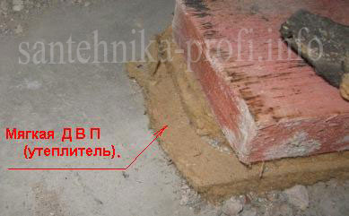
However, even when installing the heater in a niche, it is possible to reduce heat losses repeatedly by gluing a section of the wall with a special reflective thermal insulation (see Photo).
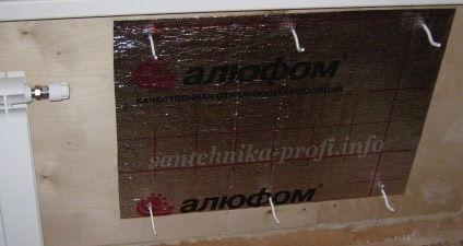
This insulation is produced (as a rule) in a roll version and is sold by the meter. It is glued to the wall with a reflective (foil) side to the radiator.
№9
Starting the system.
If you ordered a trip to the service organization, then the system should be launched - their duty (no additional charge for this should be charged). But what should be done to you, is to check all connections for possible leaks (if the heatsink was built up - on the section connections, as well as threaded, soldered, and necessarily dismountable joints, carefully examine and probe from all sides).
If the highest point of the site of the system is in your apartment - to "vent" the air after applying pressure you will also be better yourself.
On this we are closing the topic "installation of radiators".
* Once again we remind, - to disconnect the serviceable radiator both cranes (entrance and exit) for a long period of time IS NOT AVAILABLE! Will explode.
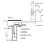
When building a private house, first of all, it is necessary to take care of a quality heating system and warming the house. It's no secret that in any heating system, one of the main roles is played by pipes. In the recent past, steel pipes for heating have been widely used, but their use has been associated with some difficulties, namely, the formation of corrosion on the walls of the pipes.
With the advent of new materials, such as and, steel pipes began to recede into the background. However, thanks to galvanizing, modern technologies were able to "defeat" corrosion and steel pipes once again took their rightful place among the heating pipes.
As you know, any heating pipes have pluses and minuses, today simply there is no ideal option for all cases of life, except maybe. They have many advantages, including durability, the ability to withstand high temperatures and many other advantages. Therefore, many experts call copper pipes the best for heating systems, but even they are not without shortcomings, such as high cost.
Consider the advantages and disadvantages of steel heating pipes.
Benefits
- High thermal conductivity.
- Ability to withstand high temperatures (melting at + 1500 ° C), without deforming.
- They are resistant to water hammers (withstand maximum pressure for 4 hours). This makes the pipes of steel suitable for the organization of centralized heating, with frequent water hammering and temperature jumps.
- Due to the zinc coating, they are not subject to corrosion. Galvanizing can increase the service life of steel by 15-20 years, besides the electrochemical protection of steel is increased.
- Mechanical strength.
Steel pipe heating system of the apartment building.
disadvantages
- Corrosion susceptibility (even galvanized pipes are corroded over time).
- Mineral substances are deposited on the inner walls, thereby creating congestion. Over time, such congestion can turn into traffic jams, completely blocking the supply of coolant. To avoid the appearance of deposits, it is necessary to use special fluids as the coolant. However, this method does not completely solve the problem. Such liquids increase the aggressiveness of the environment, which can also lead to negative consequences.
- In the case of laying steel pipes outdoors, their high thermal conductivity can be attributed to shortcomings. To avoid high heat loss, you have to use thermal insulation.
There are 2 ways of galvanizing steel heating pipes:
- Method of diffusion application. The method is based on the creation of a single crystal lattice, which is formed by the interaction of atoms of different substances with each other (steel and zinc). The whole process is carried out in powder containers. The result is a strong, resistant to the action of the coating;
- Steel pipes fall into a zinc solution, the temperature of which is about 450 ° C. Thus, the internal and external surface of the pipeline is covered with zinc, thereby increasing the service life of the material.
Note! The cost of galvanized steel is higher than the cost of metal-plastic, polypropylene and black steel.
In order to somehow prevent corrosion, pipes without galvanizing should be covered with a special paint before installation.
Installation
There are several ways to connect steel heating pipes. Each of them has its pros and cons, which must be remembered when installing the heating system. Only compliance with the technological process will avoid unpleasant surprises in the heating season.
Steel pipe with a crane on an aluminum radiator.
Ways of connecting steel pipes for heating:
Gas welding. It is mainly used for joining thin-walled pipes. As a result of gas welding, a reliable, strong connection is obtained. It is often used in close space, when the use of other methods of connection is physically impossible;
Electric welding. Most often it is used for welding of pipelines with thick walls (main heating systems). Electric welding makes it possible to heat the entire thickness of the pipe, which is difficult to achieve by gas welding;
Threaded connection. It is carried out with the help of special threaded fittings. In addition, it is necessary to cut the thread on the pipe by itself, which increases the installation time of the system.
Important! Galvanized pipes can only be mounted with threaded connections, welding is not very desirable. The fact is that in the process of welding, under the influence of high temperatures, the zinc coating simply burns out. Zinc is not able to withstand temperatures above 900 ° C.
Types of fittings for steel pipes
Thanks to various fittings, branches, turns, transitions from one diameter to another, etc. are performed. Demountable connections allow for repair and maintenance of the pipeline.
To Category: Sanitary and technical work
Connection of steel pipes on threads
The pipeline network, through which water, PE / p or gas moves under a certain pressure, consists of separate sections of steel pipes connected together. Pipeline all along, including in connection points, should be strong, dense and maintain its impermeability when extending or shortening from temperature changes.
Steel pipes can be connected on the thread and weld.
To connect steel pipes to the threads, use connecting parts (fittings) made of malleable iron and steel. The connecting parts of malleable cast iron are used for pipelines through which water or steam passes with a temperature of no higher than 175 ° C and a pressure of up to 16 kg / cm2 for passes not exceeding R / g "and up to 10 kgf / cm2 with passes from 2 to 4" .
Steel connecting parts (fittings) can be used for pipelines of all diameters at pressures up to 16 kgf / cm2. The connecting parts are made with a cylindrical thread.
Fittings made of steel do not have beads at the ends. Connecting parts of malleable cast iron with a cylindrical thread for connecting pipes in a straight line and end caps are: straight and transition couplings, connecting nuts, fittings, locknuts, plugs (Fig. 1).
To connect the pipes at an angle and the device of branches, the following connecting parts of ductile cast iron are used (figure 2): straight and transitional rectangles, straight and transitional tees, straight and transitional crosses.
Fig. 1. Connecting parts of malleable cast iron for connecting pipes in a straight line: a - straight coupling, b - transition sleeve, c - connecting nut, d - futorka, d - lock nut, e - plug
The ends of the fittings must be flat and perpendicular to the axis of the connecting part. The inner and outer threads must be clean, free of burrs and flaws and cut exactly along the centerline of the fittings. Areas with a broken thread are allowed, if their length does not exceed 10% of the thread length.
To ensure the tightness of the joint with threaded joints, use sealing material, linen, asbestos, natural linseed oil, bleach, surfacer and graphite putty.
With cylindrical threaded joints of pipes, through which cold and hot water passes (with a temperature of up to 100 ° C), a linen strand impregnated with wax or whitewash mixed with natural linseed oil serves as a sealing material.
For pipelines with a coolant temperature of more than 100 ° C, the asbestos strand, together with a linen strand, is impregnated with a graphite mixed with natural linseed oil. The thread is first smeared with surrey or whitewash. For short threads, the linen strand is wound from the second thread from the end of the pipe along the thread path by a thin even layer of "wax", without breakage. Strand must be carefully examined beforehand so that the fibers are well separated. Strand should be dry. A wound strand on top of the thread is smeared with a dilute wax. The strand should not hang from the end of the pipe or enter the pipe, as this can cause clogging of the pipeline.
The fittings must be screwed onto the pipes to failure, i.e., so that they are wedged on the last two conical thread (run) threads, which ensures a reliable connection.
In addition to the short thread, the pipes are connected and on a long thread, using drifts.
Fig. 2. Connecting parts of malleable cast iron for connecting pipes at an angle and the device of branches: a straight rectangle, b a transitional gyro, a straight tee, a g-tail with two transitions, e a straight cross, g a transitional cross, cross with two transitions
Connect the convoy in the following way. For a long thread, the lock nut and the coupling are tightened. The screwed coupling with a long thread is screwed to the end of the short thread using a sealing material. Then, the sealing material wrapped in the flagell is wound around the end of the coupling along the thread path and the lock nut is tightly fitted to the coupling. The flagellum is placed in the face of the clutch and prevents the seepage of water or steam through the threads.
In the absence of a chamfer of the sealing material in the muff, it is possible to press out the sealing nut with a lock nut, and the connection will not be sufficiently dense.
The pipe joints must be cleaned from the projecting sealing material with a saw blade.
Asbestos cord with flax is wound from the run to the beginning of the thread, which allows it to be more tightly laid on the thread and not knocked off when screwing the fittings.
Recently, instead of flax, tar and linseed oil, sealing tape on the basis of fluoroplastics - FUM tape - is used to seal the threaded joints when installing systems from water and gas pipes.
The tape of FUM consists of a fluoron 4D (80-84%) and vaseline oil for lubrication (20-16%).
Fluorlon 4D is resistant to all mineral acids, alkalis and other corrosive media.
To seal the threaded joints, a tape with a width of 10-15 mm and a thickness of 0.08-0.12 mm is used.
The surface of the tape should be flat, without ruptures and blisters.
In appearance, the tape has a white color, small shades and spots are allowed.
FUM tape is used for the installation of water supply systems, heating and gas pipelines, as well as installation of process pipelines transporting the environment with a temperature of -50 to +200 ° C.
For connection of pipelines with the use of a tape FUM preliminary threads are cleaned of pollution, wiping them with rags; then the threads are wound on the thread in the direction of the thread, as shown in Fig. 69, after which the fitting or reinforcement is wound up. For pipes with a diameter of 15-20 mm, the tape is wound into three layers, and into tubes with a diameter of 25-32 mm - into four layers.
When carrying out detachable connections (shogs) between the coupling and the lock nut, a tourniquet is wound from 3 layers of the same tape.
If the threaded connection does not provide a seal and there is a need to replace the sealing material, the thread must be well cleaned of the tape and reassembled in accordance with all the above operations.
Welding of pipes should be made, as a rule, before the sealing of the threaded joint with a tape of the FUM. If it is necessary to make a welded joint after sealing the threaded joint, the latter should be located no closer than 400 mm from the welding location.
Pipes are also connected by means of connecting nuts. At both ends of the pipes to be joined, short threads are cut and screwed onto the sealing material of the union nut union. Then, putting between the contacting planes of the fittings a gasket made of rag paperboard, boiled in linseed oil, or a paronit gasket (for steam), pull the union with a union nut.
When connecting pipes with a coupling, pipes with a reduced short thread corresponding to the length of the thread on the valve are cut.
For the connection of water and gas pipes on the thread, pipe keys of different designs are used: pipe levers, sliding and folding.
When screwing the pipes to get a reliable jamming of the fittings or the threaded fitting, it is not allowed to feed the screwed shaped part backwards to avoid breaking the joint density. If the shaped part or armature does not occupy the required position and can not be turned along the thread, the position can be corrected by disconnecting the drills on both sides of the fittings or fittings and giving them the required position; then the drivings must be reconnected. If this is not possible, you need to disassemble the connection and reassemble using new sealing materials.
Pipes are screwed in the clamps or at the installation site.
Fig. 3. Tubular keys: a - lever, b - extendible, in - mantle; 1 - fixed lever, 2-sliding lever, 3-ohm, 4 - nut, 5 - movable sponge, 6 - spring, 7 - sponge
Pipe wrenches require thorough care, systematic cleaning, lubrication of screws and articulated joints with machine oil.
It is not allowed to work with faulty keys, including keys with sponges. Such keys at work jump off the pipes and can cause bruises and injuries.
Do not work with keys whose numbers do not match the diameter of the screwed pipes, because the work is not very productive and the keys quickly become unusable.
It is forbidden to put trimming pipes on the handle of the keys to increase the force that is attached to the keys, since the handle of the keys is bent and the keys become unusable.
Water and gas pipes can be connected and welded.
Galvanized pipes are assembled only on a threaded connection, as during welding a protective layer of galvanizing is broken.
Connection of steel pipes on threads
In order to produce a connection of heating pipes, various methods and materials are used. The method of connecting these building elements with each other directly depends on which raw materials such pipes were made from. The most commonly used for installation of pipelines are pipes made of polypropylene, steel, metal-plastic and copper.
In this article, we will talk about what methods are most often used by installers when installing the above types of heating elements.
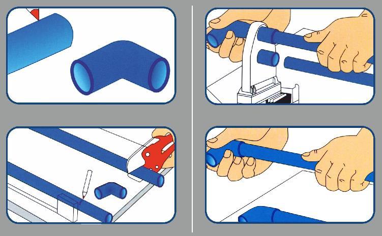
Methods of joining polypropylene pipes
If the task is to equip heating with small diameter plastic pipes (up to 63 mm), in practice there are two ways to connect such pipes:
- socket fusion - in this case one pre-expanded end of the pipe is placed in the other;
- socket welding - here the ends of the two elements are connected together by means of a coupling.
In the case of docking pipes with a large diameter (from 63 mm) resort to the use of splicing welding. This method of installation does not require additional connecting elements, while maintaining an excellent degree of fixation of the pipes. You can also use suitable fittings (socket welding). In the presence of pipes with a diameter of 40 mm it is more convenient to use manual welding, but elements of a larger size are docked with the help of a special apparatus that pre-aligns.
Immediately before the start of the installation of the heating system, once again carefully consider the entire process of assembling the pipeline. This will avoid at the time of work undesirable nuances that affect the final quality of the assembly of the heating system.
Here we will outline the basic nuances of how to make the connection of plastic heating pipes:
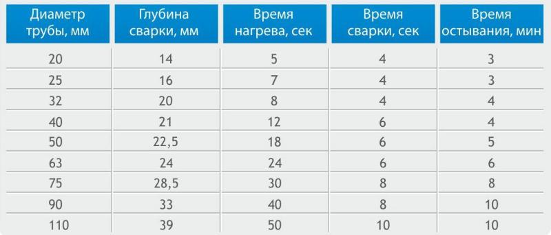
- The optimum heating time for the soldering apparatus is 5 seconds.
- The recommended melting point of polypropylene is 270 ° C. This parameter can be achieved with a special toggle switch installed on the welding machine.
- It should be noted that the technology of connecting the pipes of the heating system will vary depending on the place and time of the year. So, during periods of minus temperatures or when installing a heating structure outdoors, the heating time of the soldering iron pipe should be slightly increased or the temperature for melting polypropylene products raised.
- In the case of docking of pipes of larger diameter, the melting time of the material will also increase somewhat.
- The recommended time for fixing large diameter elements to each other after heating them is 30 seconds or more.
- After reaching the required temperature, the nozzles - for the outer and inner dimensions of the cross section of the pipes - are simultaneously worn and heated by the coupling parts (coupling, pipe).
- At the time of the heating process, "flanges" are formed on the heating elements.
- As a result of the heating process, both parts are removed from the nozzles and joined together by uniformly pressing them lightly on both sides to one another and fixing in this position. Any rotations and excess movements during joining of elements are inadmissible, since this can disrupt the resulting seam.
- The connected components should be held for 30 seconds for more reliable grip of parts of the heating system. It must be added that the rim should be flat over the entire length of the joint.
After complete cooling, the connected parts are ready for use.
Ways of joining pipes made of metal-plastic and PEX-pipes
Metal-plastic elements and PEX-pipes often join together using the same method. Here we describe in detail the technology of installing the heat pipe from the above materials.
Related articles