Rectangular heating stove. Heating rectangular stove
Figure 36 (the end). Laying T-shaped furnace
5th row - laying of the grate.
6th - 9th row - in front of the spread firebox.
At the 8th and 9th rows, the firebox is connected to the fire chamber.
10th row - put the ceiling over the furnace door.
The 11th - 13th row - the firelighter's overlap device at the outlets, in the rear part the continuation of the laying of the fire chamber and the lifting channels.
The 14th row - from the front of the facade they put a clean door, in the front part an upper chamber is formed. The support column of 1/2 brick divides it into the actual chamber, connecting channels and the base of the chimney.
16th - 17th row - laying of rows differs from the previous ones only in the arrangement of bricks for dressing vertical seams.
18th - 21st row - through the supporting column lay the base of the dissection between the upper chamber and the chimney.
The 22nd - 23rd row - overlap the lower combustion chamber.
24th - 25th row - vertical lifting channels are connected to the upper chamber via a horizontal channel, a cleaning door is installed to clean the horizontal channel.
26th - 29th row - the device shut off the furnace.
On the 28th row they put a view valve, starting from the 30th row, they put a chimney with an internal channel of 25 × 13 cm.
Heating rectangular furnace of increased heat transferIt is used for heating large rooms. The furnace is simple in structure, it can burn any solid fuel. Flue gases from the firebox rise through the vertical channel, but do not reach the stopping furnace, and, reflecting from the intermediate ceiling, descend to the bottom of the furnace, where they get into the rear lift channel through the roll-up through which they rise to the stove. After a series of revolutions, the gases go down the chimney.
For the laying of the furnace requires 580 pieces of bricks.
The laying is the same as the rectangular heating furnace, with the exception of the 32nd and 36th row, where smoke valves are installed.
Furnaces of MVMS of the increased warming upThe frame furnace MVMS – 61 is small in size, but in terms of heat transfer it is not inferior to massive furnaces. The dimensions of the furnace are 40 × 40 cm, height 146 cm. Any solid fuel is burned in the firebox of the furnace.
The flue gases from the firebox rise through the front channel to overlap, then they descend through the rear channel to the level of the nozzle connecting the furnace with the chimney.
The furnace is attached to the chimney in the wall or to the root pipe.
For the laying of the furnace requires 55 pieces of bricks. The base of the furnace is roofing steel, a layer of felt moistened in clay is laid on it. The walls and the overlap of the firebox spread of refractory bricks.
The frame of the furnace is placed directly on the floor, strictly according to the plumb line; if the flooring is wooden, asbestos or felt are laid under the stove, and the top is a sheet of roofing iron; on the corners, welded at the bottom of the frame, lay the base, lay on it the 1st row. 2nd row - lay out space for a sliding ash box. The subsequent laying is carried out according to the drawings and relief images.

Figure 37. Rectangular heating furnace of increased heat transfer
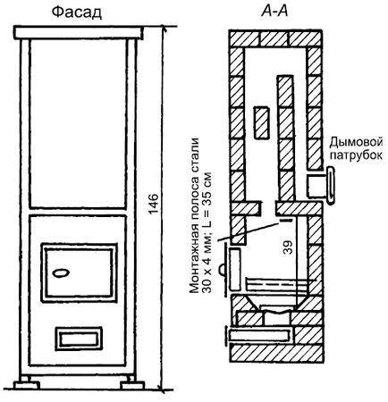
Figure 38. Furnace MVMS – 61 increased warming up

Figure 38 (continued). Furnace MVMS-61 increased warming up Furnace MVMS-63 enhanced heating
The size of the oven on the plan is 52 × 52 cm, height is 155 cm.
114 bricks are required for the laying of the furnace.
The furnace is attached to the chimney in the wall or to the root pipe. The installation is the same as that of the stove MVMS – 61.
Round furnaces in steel casesHeating furnaces, which are circular in plan, are almost always enclosed in a case. Round ovens retain heat well and are not cooled, even if the view valve is not covered.

Figure 39. Masonry stove MVMS – 61 increased warm-up


Figure 39 (continued). Laying furnace MVMS-61 increased warming up
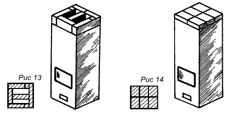
Figure 39 (end). Laying furnace MVMS-61 increased warming up
Flue gases from the firebox through the hilo in the middle of the overlap enter the cap (chamber). Part of the heat is given to the chamber walls and furnace overlap, while the remaining gases, when cooled, descend along the space near the furnace walls into a horizontal horseshoe-shaped smoke channel connected to chimney. 
Figure 40. Furnace MVMS-63 enhanced heating


Figure 40 (continued). Furnace MVMS-63 enhanced heating
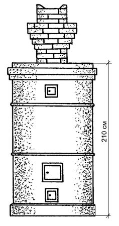
Figure 41. The device of a heating round furnace in a metal case: 1 - a pass wall; 2 - base

Figure 41 (end). The device of a heating round furnace in a metal case: 1 - a pass wall; 2 - base
The cold air entering the furnace through the furnace and blowing doors, as heavier than the one in the bell, is held in the lower part of the furnace without cooling it.
Such furnaces are in demand now. It is believed that increasing the size of the furnace leads to an increase in the heat it gives off. This is true only for heat accumulation. But the heat does not always justify the cost of fuel. If at the same time the fireboxes are hidden behind the smoke line system and they are not the outer walls of the furnace, then the internal parts of the furnace are heated more than the outer walls. After the view is closed, heat transfer stops. Accumulated heat goes into the chimney. Small-sized furnaces with walls in 1/4, 1/2 of the brick are heated with a small amount of fuel and the accumulated heat is given into the room.
The duration of the firebox is 30-40 minutes, a massive furnace 1.5-2 hours. The longer the stove heats up, the more heat goes into the chimney.
Heating rectangular stove.
The dimensions of the furnace in terms of 51 × 89 cm, height 238 cm. It can burn any fuel. The firelighter is located in the lower part of the furnace, its walls are the walls of the furnace itself, which provides the lower heating. Flue gases enter the vertical channel, reflecting from the ceiling. For the laying of the furnace is required: brick - 355 pieces, including refractory 110 pieces.
The 1st row - in front of the bricks lay out butting, the corner bricks break up to 3/4 of the bricks, and the upper faces of the two middle ones cut off, forming a slope inside the masonry to the bottom of the ash pan. The slope is shown in section along the AA. In the back of the row, the space between the outer wall of the furnace and the back wall of the ash pan is covered with dry sand. Backfilling is done up to the 3rd row inclusive.
2nd row - in the center of the front wall put the blower door. Corner bricks on the right and left of it up to 3/4 bricks, the rest of the masonry from full-sized bricks.
3rd row - after laying the bricks of this row, a steel strip 35 cm long and 4 cm wide is laid over the front part of the ashpit, which is the support for the brick covering the part of the ashpit on the next row.
4th row - overlap the front of the ash pan. In the back of the row, the backfill is bricked up.
5th row - they put a grate on the hole above the ashpit. Bricks hemmed in from behind and in front form slopes for coals rolling on the grate.
6th row - put the furnace door in the center of the front wall. The bricks of the back wall are sloped inside and form one inclined plane with the bricks of the previous row.
7th - 12th row - laying of the firebox.
The 13th row is the laying of issues for the overlapping of the firebox. The front of the side walls lay out of 3/4 brick.
14th - 15th row - overlap over the firebox. A hole is left in the rear part connecting the firebox with a vertical channel (khilo).
The 16th row - put the door clean, behind her block "half", laid on the edge. The shelf behind the door is covered with a layer of clay-cement solution to completely isolate the firebox from the smoke channels located above.
17th - 20th row - laying of vertical smoke channels.
The 21st - 22nd row - connects the lifting smoke channel coming from the firebox with the downstream channel. Here, the gases from the firebox roll over through a cut that separates the channels into the middle lowering channel, through which they reach the 18th row and through a subtraction fall into the front lift channel.
23rd - 24th row - overlap the middle and rear channels.
25th - 26th row - put a door to clean the bottom of the chimney, resulting in a spin from the middle channel of the second tier to the chimney.
Figure 31. Rectangular heating stove.
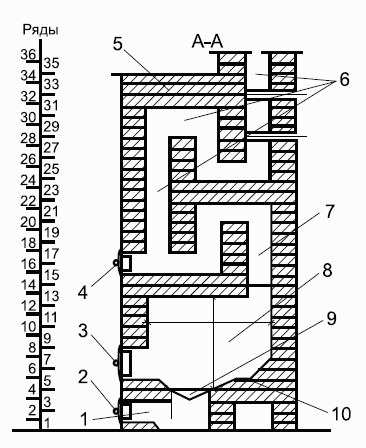
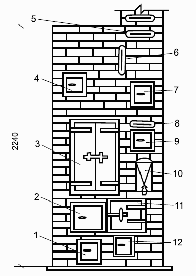
Figure 31. Rectangular heating furnace (continued): 1 - ashpit; 2 - double door; 3 - fire door; 4 - cleaning; 5 - overlapping; 6 - chimneys; 7 - heat channel; 8 - firebox; 9 - grate; 10 - under.
27th - 30th row - laying of smoke channels of the second tier, of which the back is the beginning of the chimney. On the 28th row they put the first view valve.On the 30th row complete the second cycle of revolutions. Here, the flue gases from the front elevation channel pass into the middle lowering channel and, after descending along it to the undercut, on the 26th row enter the chimney.31st row - lay out the issues for shutting off the stove.32nd - 34th row - overlapping furnace. Bricks are laid so that all vertical joints of the first row are blocked.On the 32nd row put the 2nd latch valve. Installing two view valves reduces furnace heat loss. In the absence of valves, a round view is put on the 32nd row.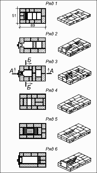
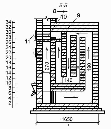
Figure 32. Laying heating rectangular oven.
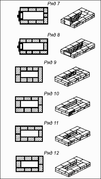
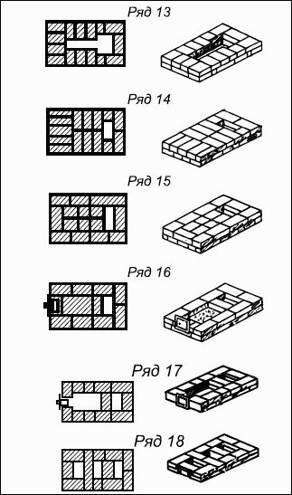
Figure 32 (continued). Laying heating rectangular furnace.
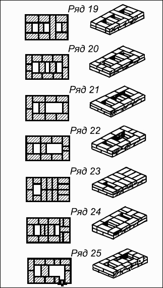
Figure 32 (continued). Laying heating rectangular furnace.
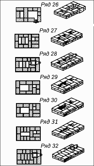
Figure 32 (continued). Laying heating rectangular furnace.
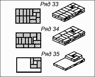
Figure 32 (end). Laying heating rectangular furnace.
35th row and the subsequent - laying chimney. Chimney laying
The pipe at the floor should have a groove (fluff), an expanded part, which is laid out gradually.The 1st row is laid out in “gear” - 6 bricks.2nd row - brick is prickled into two parts along the length and laid with non-chipped parts inside. Bricks are laid around flat, increasing dimensions by 12 cm.3rd row - lay out of two rows of bricks, laid flat, the size of the masonry increase by another 14 cm.4th row - first put into 1/4 bricks, laying them in length, and then laying around 2 rows flat.5th row - spread out of three rows of bricks flat, the size of fuzziness increase.6th-8th row - lay without increasing the size of fuzz. Laid out the cutting, put the pipe in 1/2 brick within the attic.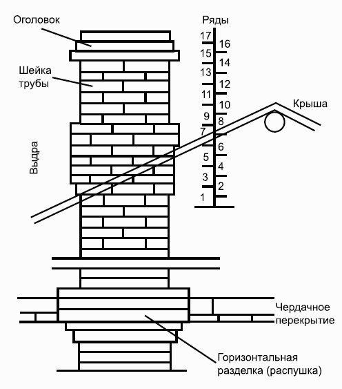
Figure 33. Chimney deviceLaying otters, necks, pipe end
Laying out the pipe to the roof, put the otter, neck, tip.1st row - perform in 6 bricks "six".2nd row - from the side of the descent put out 3/4 bricks, letting them in by 60 mm on the pipe.3rd row - put so that the three-foursome bricks were laid flat with a slight lengthening of this part.The 4th row has the same length, but the width of the masonry increases.5th-6th row - is expanding otter clutch.The 7th row is completely displayed on the roof and expands on all sides, laying is carried out from brick to the edge and flat.8th row - put the same way, only with a different ligation of the seams. On this otter laying is over.9th row - laying of the neck is performed in the "six", the number of rows from the 9th to the 19th.The 20th row is the laying of the head (it has 2-4 rows), the top row is mown.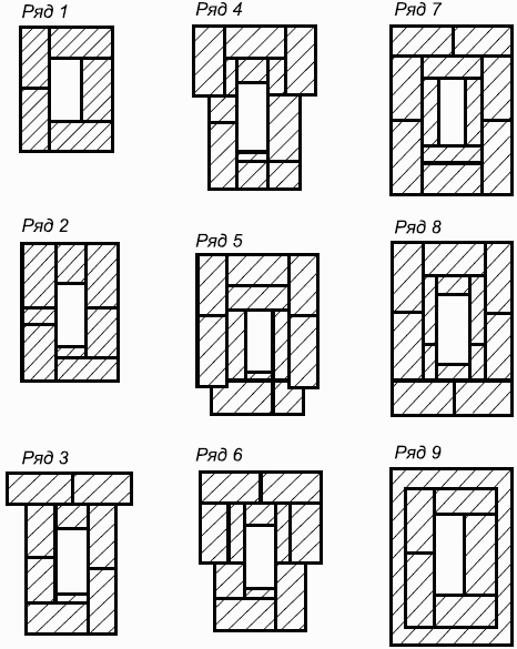
Figure 34. Chimney masonryT-shaped heating stove
The stove is convenient for location in partitions and is designed for heating large rooms. The firelighter is used to burn any kind of fuel. The walls of the firebox are the walls of the furnace. From the firebox flue gases through the hilo enter the rear chamber.Having removed some of the heat to the walls and reflected from the overlap of the chamber, the gases descend and enter the lifting channels connecting the rear chamber with the upper one.After cooling, the flue gases are lowered into the channels connecting the upper chamber with the chimney.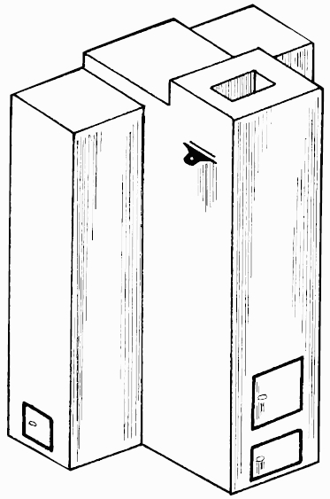
Figure 35. T-shaped heating furnace.
490 bricks are required for masonry. 1st row - in the front of the bottom of the ash pan is formed, a brick lying in the blowing door is beveled.2nd row - they put a blower door, a channel is formed in the back part, which is closed on one side by a blank wall, on the other - by a clean door.3rd row - the bricks in the front protruding part are laid out so that when laying the next row, the dressing of vertical seams is observed.The 4th row - the walls of the ash chamber are 18 cm thick, an increase in wall thickness is necessary so that after the grate is laid, there are no gaps between its edges and the walls of the firebox. In the back of the cut begins, separating the lifting vertical channels.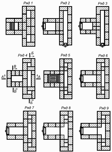
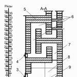
Figure 36. Laying T-shaped furnace.
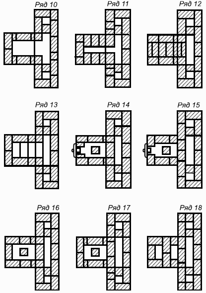
Figure 36 (continued). Laying T-shaped furnace.
Figure 36 (the end). Laying T-shaped furnace.
5th row - laying of the grate. 6th - 9th row - in front of the spread firebox.At the 8th and 9th rows, the firebox is connected to the fire chamber.10th row - put the ceiling over the furnace door.The 11th - 13th row - the firelighter's overlap device at the outlets, in the rear part the continuation of the laying of the fire chamber and the lifting channels.The 14th row - from the front of the facade they put a clean door, in the front part an upper chamber is formed. The support column of 1/2 brick divides it into the actual chamber, connecting channels and the base of the chimney.16th - 17th row - laying of rows differs from the previous ones only in the arrangement of bricks for dressing vertical seams.18th - 21st row - through the supporting column lay the base of the dissection between the upper chamber and the chimney.The 22nd - 23rd row - overlap the lower combustion chamber.24th - 25th row - vertical lifting channels are connected to the upper chamber via a horizontal channel, a cleaning door is installed to clean the horizontal channel.26th - 29th row - the device shut off the furnace.On the 28th row they put a view valve, starting from the 30th row, they put a chimney with an internal channel of 25 × 13 cm.Heating rectangular furnace of increased heat transfer
It is used for heating large rooms. The furnace is simple in structure, it can burn any solid fuel. Flue gases from the firebox rise through the vertical channel, but do not reach the stopping furnace, and, reflecting from the intermediate ceiling, descend to the bottom of the furnace, where they get into the rear lift channel through the roll-up through which they rise to the stove. After a series of revolutions, the gases go down the chimney.For the laying of the furnace requires 580 pieces of bricks.The laying is the same as that of a rectangular heating furnace, with the exception of the 32nd and 36th row, where smoke valves are installed.Furnaces of MVMS of the increased warming up
Frame furnace MVMS-61 has a small size, but in terms of heat transfer is not inferior to massive furnaces. The dimensions of the furnace are 40 × 40 cm, height 146 cm. Any solid fuel is burned in the firebox of the furnace.The flue gases from the firebox rise through the front channel to overlap, then they descend through the rear channel to the level of the nozzle connecting the furnace with the chimney.The furnace is attached to the chimney in the wall or to the root pipe.For the laying of the furnace requires 55 pieces of bricks. The base of the furnace is roofing steel, a layer of felt moistened in clay is laid on it. The walls and the overlap of the firebox spread of refractory bricks.The frame of the furnace is placed directly on the floor, strictly according to the plumb line; if the flooring is wooden, asbestos or felt are laid under the stove, and the top is a sheet of roofing iron; on the corners, welded at the bottom of the frame, lay the base, lay on it the 1st row. 2nd row - lay out space for a sliding ash box. The subsequent laying is carried out according to the drawings and relief images.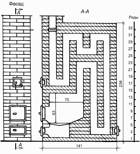
Figure 37. Rectangular heating furnace of increased heat transfer.
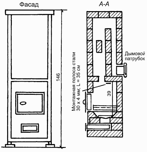
Figure 38. Furnace MVMS-61 increased warming up.
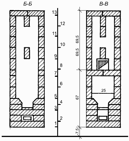
Figure 38 (continued). High-temperature furnace MVMS-61Furnace MVMS-63 enhanced heating
The size of the oven on the plan is 52 × 52 cm, height is 155 cm.114 bricks are required for the laying of the furnace.The furnace is attached to the chimney in the wall or to the root pipe. The installation is the same as for stove MVMS-61.Round furnaces in steel cases
Heating furnaces, which are circular in plan, are almost always enclosed in a case. Round ovens retain heat well and are not cooled, even if the view valve is not covered.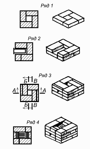
Figure 39. Masonry furnace MVMS-61 increased warm-up.
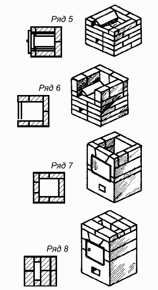
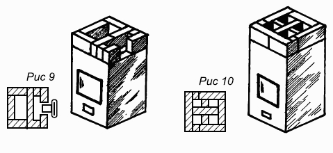
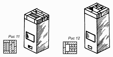
Figure 39 (continued). Masonry furnace MVMS-61 increased warming up.

Figure 39 (end). Masonry furnace MVMS-61 increased warming up.
Flue gases from the firebox through the hilo in the middle of the overlap enter the cap (chamber). Part of the heat is given to the walls of the chamber and the furnace overlap, while the remaining gases, when cooled, descend along the space at the walls of the furnace into a horizontal horseshoe-shaped smoke channel connected to the chimney. 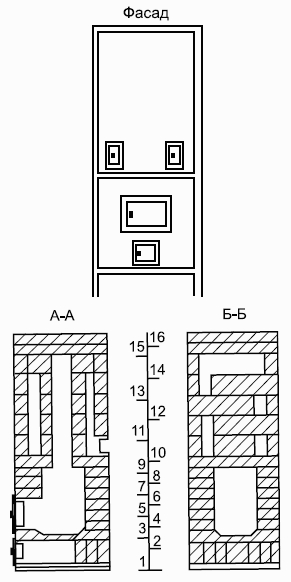
Figure 40. Furnace MVMS-63 enhanced heating.
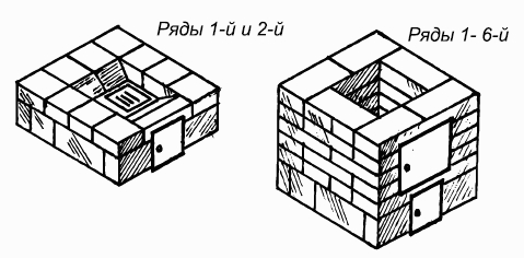
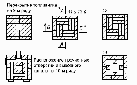
Figure 40 (continued). Furnace MVMS-63 enhanced heating.
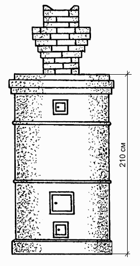
Figure 41. The device of a heating round furnace in a metal case: 1 - a pass wall; 2 - base.
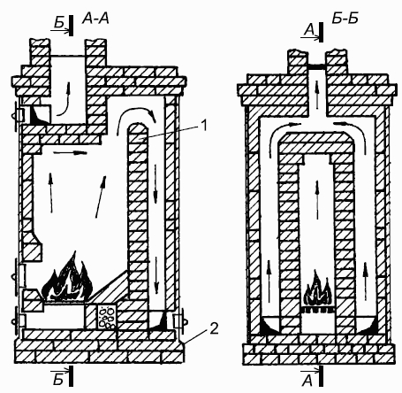
Figure 41 (end). The device of a heating round furnace in a metal case: 1 - a pass wall; 2 - base.
The cold air entering the furnace through the furnace and blowing doors, as heavier than the one in the bell, is held in the lower part of the furnace without cooling it. Heat transfer begins shortly after firing.The heating furnace is round, brick in a metal case The height of the furnace is 229 cm, diameter 65 cm.For the masonry of the furnace you will need 260 pieces of bricks. The firelighter is designed to burn any solid fuel.The stove joins the chimney in the wall or to the root pipe.
Figure 42. Laying heating round furnace in a metal case.
Figure 42 (continued). Laying heating round furnace in a metal case.
Figure 42 (continued). Laying heating round furnace in a metal case.
Figure 42 (continued). Laying heating round furnace in a metal case.
Figure 42 (continued). Laying heating round furnace in a metal case.
Figure 42 (continued). Laying heating round furnace in a metal case.
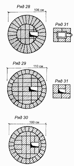
Figure 42 (continued). Laying a round heating furnace in a metal caseRound oven in a metal case with helical smoke turns
The height of the furnace is 209 cm, the diameter of the base is 100 cm, the diameter of the heat transfer part is 70 cm. Heat transfer begins 20 minutes after the kindling. The ash chamber is located at the base of the furnace, so the furnace warms up more at the bottom. Flue gases from the firebox enter the first annular channel.Making a circular path, heat strikes the walls of the furnace, heating them. Then the gases pass through the central channel to the 2nd annular channel, then to the 3rd one, from it to the chimney.For the laying of the furnace you need 480 pieces of bricks.Laying features:the first 4 rows are not okozhuhany. Extreme along the perimeter of the bricks are sloping around. Thorough bricks do not have to be done. The construction of the furnace begins with the definition of its center on the foundation. Draw a circle with a radius of 50 cm, inside it put the 1st row of bricks.When laying the next three rows of the base, they put a blower door, lay the ash pan.On the 4th row put the grate. This row is laid out on the level, because it relies on the first side of the casing.On the basis of putting the first rye with a fire door. If the centers of the tsarga and the base coincide, then the part of the base protruding from under the tzorgi forms a belt 5 cm wide.The tsarga is calibrated with a plumb not less than four positions after laying for the stability of a number of bricks inside the tsarga.The bricks have a rectangular shape, and put them in a circle, in the joints between them form voids. Fill them with fine gravel mixed with clay solution.The space between the face of the brick and the casing is poured with clay mortar. Air pockets between the casing and masonry reduce thermal conductivity.
Figure 43. A round oven in a metal case with helical smoke turns.
The next cover of the casing is set when the lower bark is lined with brick. The masonry of the walls of the central channel is made of bricks, hewn onto a wedge. Rows 14, 15, 17 do not differ from 8, 9, 10th, but are displaced with respect to them by 135 °. The cross section of the channel of the chimney 15 × 13 cmHeating and cooking stoves
Heating and cooking stoves except heating are intended for cooking food, baking bread, heating water.These include: Russian stove, cooking stove, bakery oven, combined heating and cooking stove.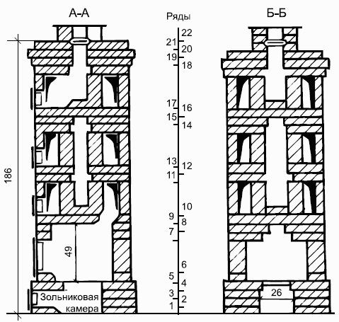
Figure 44. The device of a round furnace in a metal case with spiral-shaped chimneys.
The heating parts of the heating-cooking stoves come with different smoke extraction systems. A large amount of heat is given to the room through the oven and oven, that is, the front of the oven has a greater heat transfer than the rest.This should be considered when placing such furnaces.Water boxes are set so that the heating occurs due to the heat, waste gases.Ovens, so that they do not overheat, are covered with a layer of clay and covered with walls of bricks "on the edge".Russian stove
It has an advantage over a conventional oven. In the summer, it is used for cooking with the release of flue gases directly into the chimney. In winter, flue gases are allowed directly into the shield, heating it.The dimensions of the furnace are 153 × 165 cm, height 238 cm.A large mass of the furnace requires an appropriate foundation of rubble stone and concrete.For ease of use, bricks are recommended to be laid out in order without a solution.Each row is checked for horizontal, square, vertical.Particular attention is paid to the ligation of the seams, the cleanliness of the channels and the inner side and the filling of the sutures with a solution. The main part of the Russian stove is the cooking chamber.The lower plane of the cooking chamber is called the hearth, the overlap of the chamber is arch, the hole in the front wall through which wood is loaded is the mouth, the area in front of the mouth is sixth; in the lower part of the furnace is the undercut.There is no grate in the Russian stove, so coal does not burn in it. The bottom of the stove does not get warm up to the hearth, so it is cold on the floor and even ice is formed on the floor near the entrance door.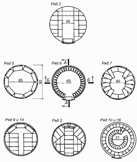
Figure 45. Laying a round furnace in a metal case with spiral-shaped chimneys.
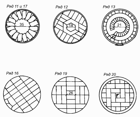
Figure 45 (end). Laying a round furnace in a metal case with spiral-shaped chimneys.
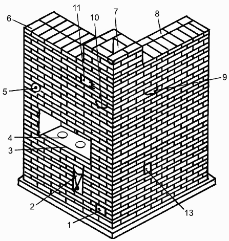
Figure 46. Russian stove: 1, 13 - cleaning; 2 - water box; 3 - hearth; 4 - cast iron stove; 5 - samovar d = 100 mm; 6 - overlapping; 7 - pipe; 8 - overlapping of the heating shield; 9, 10 - latches; 11 - view, closed by the door; 12 - waterproofing (see Figure 47).
For the laying of the furnace requires 2000 pieces of bricks.
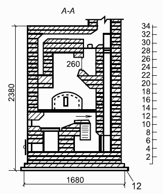
Figure 47. The device of the Russian stove.
Laying features.1. Monitor the cleanliness of the channels from the inside.2. Complete filling of the joints with the solution.3. Carefully bandage the sutures.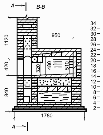
Figure 47 (continued). The device of the Russian stove.
4. Lay out the selected bricks in order at first without a solution. 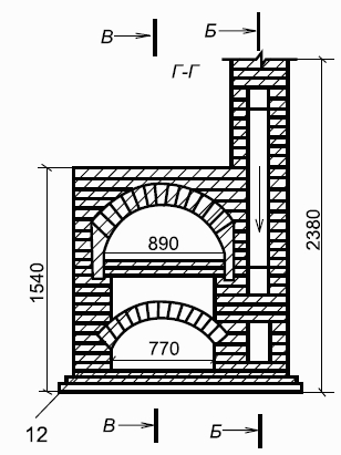
Figure 47 (continued). The device of the Russian stove.
The 1st row is the size of 153 × 165; in order, the outer sides of the row are made of a whole brick, and the middle is in halves and quarters. 2nd row - put in the form of walls of different thickness with a well between them.3rd row - installation of the blower door, ash pan installation and cleaning channel. The sharp angle of the channel is cut or fixed.4th row - put the same as the 3rd row.
Figure 48. Masonry Russian furnace.
5th row - blowing door and cleaning shift masonry. The brick laid on the side walls from the inside of the well is being cut off to form the heels necessary for laying the vault.
6th row - lay the arch with a slight rise, reaching up to the 8th row, with installation of a water-heating box from the front of the furnace.
Figure 48 (continued). Masonry Russian stove.
7th row - lay out the walls and block the horizontal channel, leaving three holes: one - near the water heating box; two - in the heating shield for the formation of vertical channels.
Figure 48 (continued). Masonry Russian stove.
8th row - cut off the edges of the bricks, stacked above the ashpit.
Figure 48 (continued). Masonry Russian stove.
The 9th row - masonry as in order, on the left side put the furnace door, as a result the firebox of the stove and shield is formed.
Figure 48 (continued). Masonry Russian stove.
The 10th row - the water heating box is covered with two bricks with the sides cut off (section B-B), they are cleaned and 3 channels are left.
Figure 48 (continued). Masonry Russian stove.
11th row - arrange a horizontal channel, above which will be located 3 vertical channels of the shield.
Figure 48 (continued). Masonry Russian stove.
The 12th row is solid masonry from the walls and hearth with laid cast-iron plates with two burners and three channels. At the beginning lay the walls of the furnace, then put plates on a layer of clay. A corner is fastened to the front wall, which protects this row of masonry and the laid plates from destruction.
Figure 48 (end). Masonry Russian stove.
The 13th row - put the walls of the cooking chamber with a thickness of 3/4 of a brick, lay the brick on the outside, and on the inside on the edge. In this row lay the shield and the front wall of the cooking chamber with a hole - the mouth through which fuel is loaded into the chamber. 14th row - put in order, and then put the formwork on paper-covered under, formwork is needed to lay the vault of the cooking chamber, taking into account the elevation of the mouth by 480 mm, at the back wall by 510 mm.The 15th row - laying of a brick arch “on the edge” with rolling in a brick due to the thickening of the outside seam.The 16th - 17th row - is laid out in order, in the 17th row they cover the mouth, i.e. they close the front wall.18th row - the completion of the laying of the vault of the cooking chamber. Begin to spread stove width from 150 to 200 mm, height 210 mm. The stove is covered with the last row of masonry and a whole brick. Partitions separating the stoves must be at least 1/2 brick.The 19th row is a masonry in order, on the left side of the stove, in the re-tubing, brick is being cut off under a small overlap for the samovar channel. The bricks adjacent to the vault are scrapped so that they lie more closely on it. The opening of the fracture is gradually shortened by laying a brick.20th - 21st row - laying with overlapping for the formation of the bottom of the channel under the samovar.The 22nd row - line the top of the furnace under the roof (section BB). From the 13th to the 28th row, all 5 channels retain their size.23rd row - laying in order.24th row - extend the re-tubing to the size of the 19th row, laying the channel for the samovar.25th - 26th row - laying is the same as in the 24th row.27th row - overlap overlap to form a horizontal channel, install a valve in the pipe channel, a valve in the channel of the shield.The 28th row is the installation of a door and a view that covers the pipe after the heating chamber of the cooking chamber (sections AA, BB).The 29th row is the overlap of five vertical channels, 3 channels remain, 2 extreme - long, medium - unchanged.30th row - has two long channels.The 31st row - forms a horizontal channel from the samovar, so that this channel is blocked, it is narrowed down, laying 1/4 of a brick from the inside.The 32nd row - cover all channels, excluding the pipe channel size 25 × 38 cm.33rd row - narrow this channel to a size of 25 × 25 cm.The 34th row - laying of the chimney in the "six" with a channel size of 25 × 25 cm.Improved Russian oven "Housekeeper"
The furnace is smaller in size than the previous furnace, simple in structure. It has two fireboxes: the main (large) and additional (small).The flue gases from the large firebox come into the first section of the underfloor chamber, then through the rolls into the second section, and from there through the slot into the hearth into the upper cooking chamber.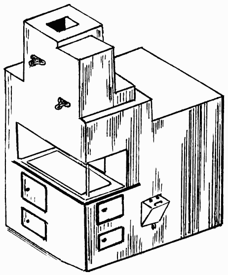
Figure 49. Improved Russian oven "Housekeeper".
Passing over the arch and through the hole in the front of the arch, fall into the chimney. The flue gases generated in the small firebox first enter the large firebox, and then travel the same way to the chimney. The furnace is equipped with a vent valve and a hot-water box. Rules of operation are the same as in the previous furnace. For laying will need 750 pieces of bricks. Heating and cooking stove I. F. Volkova without a chamber for baking bread
The dimensions of the furnace in terms of 109 × 89 cm, height 244 cm.For laying, 520 pieces of red brick will be required, including 100 refractory pieces. The stove has a cooking chamber, from which a hood is made, an oven, and a water-heating box. The stove is heated in the winter and in the summer.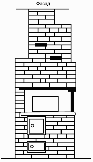
Figure 50. Improved Russian oven "Housekeeper".
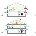
When firing in the winter gas, reaching the water heating box, they get into the 1st, and then into the 2nd chambers, in turn, they are heated and out through the valve into the chimney (section AA, BB). When the firebox in the summer hot gases pass under the stove, oven and hot water box, and then fall into the chimney. 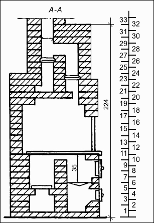
Figure 51. The device housekeeper.
First lay out the foundation with waterproofing, and then proceed to the laying of the actual furnace.

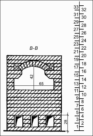
Figure 51 (continued). Device furnace "housekeeper."
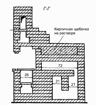
Figure 51 (end). Device furnace "housekeeper."
1st row - solid with a recess for the ash pan. To make it easier to remove the ashes, the brick is being cut off towards the ashpit. 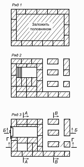
Figure 52. Housekeeper furnace masonry without a water heater box.
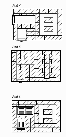
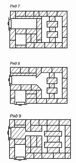
Figure 52 (continued). Laying the furnace "housekeeper" without water heating box.
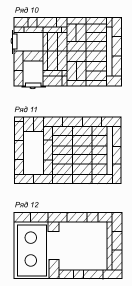
Figure 52 (continued). Laying the furnace "housekeeper" without water heating box.
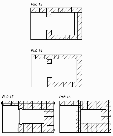
Figure 52 (continued). Laying the furnace "housekeeper" without water heating box.
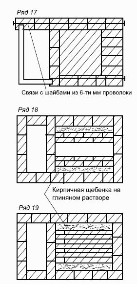
Figure 52 (continued). Laying the furnace "housekeeper" without water heating box.
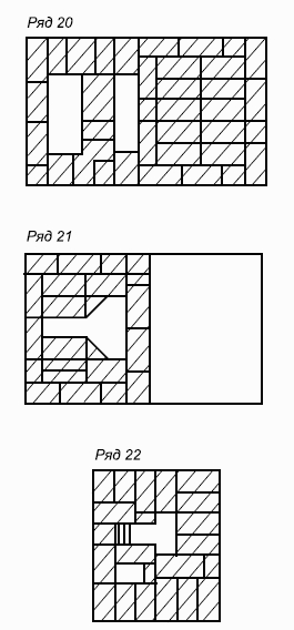
Figure 52 (continued). Laying the furnace "housekeeper" without water heating box.
Figure 52 (continued). Laying the furnace "housekeeper" without water heating box.
Figure 52 (continued). Laying the furnace "housekeeper" without water heating box.
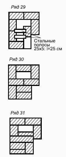
Figure 52 (continued). Laying the furnace "housekeeper" without water heating box.
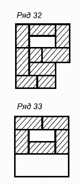
Figure 52 (end). Laying the furnace "housekeeper" without water heating box.
2nd row - put, as shown in the figure, with the installation of the ash pan door. 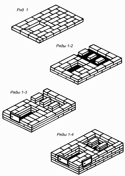
Figure 53. Housekeeping oven "housekeeper" with a water box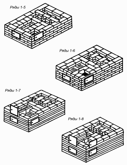
Figure 53 (continued). Laying the furnace "housekeeper" with hot water box.
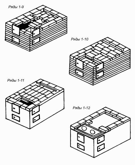
Figure 53 (end). Laying the furnace "housekeeper" with hot water box.
In fig. 54: 1 - blew; 2 - firebox; 3 - cooking chamber; 4, 9, 12 - cleaning; 5 - smoke damper, closing the furnace after the furnace; 6 - valve opened in winter; 7 - samovar; 8 - valve opened in summer; 10 - water box; 11 - oven; 13 - metal mesh in the frame; 14 - waterproofing; 15 - closed camera; 16 - channel for ventilation of the chamber; 17 - cast iron plates.
3rd row - on the right side install the cleaning door. 4th row - put with the installation of the door for cleaning on the other side of the furnace and the device ash chamber.5th row - overlap one purge and put a grate in it.6th row - install the furnace door and oven.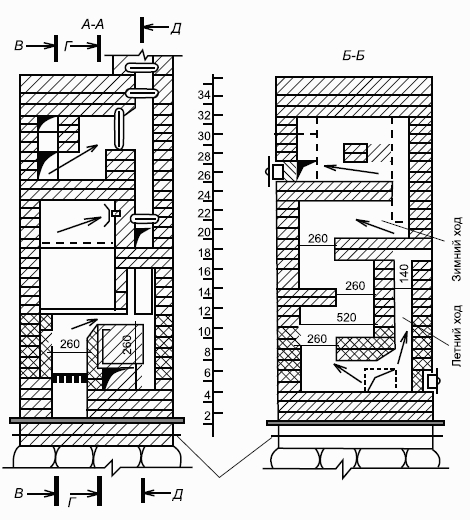
Figure 55. The device of the heating-cooking oven I. F. Volkov without a chamber for baking bread.
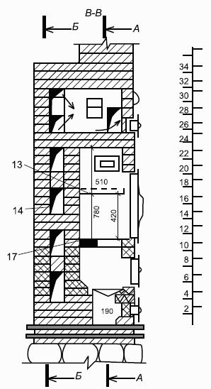
Figure 55 (continued). The device of the heating-cooking oven I. F. Volkov without a chamber for baking bread.
6th - 7th row overlap the long channel, forming a shorter one. 9th row - scrape the upper part of the oven wall and change the location of the channels.10th row - smeared with clay top of the oven.
It is located in its lower part, and its walls are at the same time the walls of the furnace, due to which mainly lower heating is achieved.
Rectangular, model 1: a - device; b - the sequence of laying
Materials
- ordinary brick - 245 pcs .;
- refractory brick - 110 pcs .;
- ordinary clay - 0.2 m3;
- Chamotte clay - 12 kg;
- sand - 0.2 m3;
- door of the furnace 250 x 200 mm - 1 pc .;
- single door 130 x 140 mm - 1 pc .;
- door clean 130 x 140 mm - 2 pcs .;
- View valve 130 x 130 mm - 2 pcs .;
- grate 250 x 250 mm - 1 pc .;
- Only waterproofing - 100 m2.
1st row - three-quarter bricks are put in the corners, the front wall is laid out by poking. Two medium bricks are being cut down along the upper edges, making a slope towards the bottom of the ash pan (section AA). The space between the back wall of the ashpit and the outer wall of the furnace is covered with dry sand up to the 3rd row inclusive.
2nd row - install a blower door in the center of the front wall, on the sides of it put three-quad, further lead masonry of full-sized bricks.
3rd row - build masonry. When all the bricks are laid, a 4 x 35 cm steel strip is placed over the front of the ash pan.
4th row - an overlap of ash chamber is placed on a steel strip. In the back of the top of the sand backfill lay a brick.
5th row - establish the grate above the ashpit. The bricks, located in front and behind of it, are being cut off so that a bevel for rolling the coal onto the grate is obtained.
6th row - install the furnace door. The bricks of the back wall are being cut down so that their slopes are in the same inclined plane with the slopes of the bricks of the previous row.
7–12th row - laying of the firebox in 1/2 bricks with obligatory dressing of the seams.
13th row - editions for the overlapping of the firebox on the front wall and part of the side walls. Laid out of three-quarter.
14th and 15th rows - laying of the ceiling above the fuel chamber. A hole is left in the back, which serves to connect the firebox with a vertical channel.
16th row - installation of the cleaning door. The right door rests on 1/2 brick, put on the edge. To isolate the firebox from the upstream smoke channels, the shelf behind the door is covered with clay-cement solution.
The 17th – 20th rows - vertical smoke channels are put.
The 21st and 22nd rows - the lifting and lowering channels are interconnected. Here ends the dissection separating the rear lift channel and the middle lowering channel.
The 23rd and 24th rows - laying the overlap of the rear and middle channels.
25th and 26th rows - installation of a cleaning door. Subversion from the middle channel of the second tier to the chimney.
The 27th row is the beginning of the laying of the smoke channels of the second tier.
The 28th row is the installation of a reed valve.
The 29th – 30th rows - laying of smoke channels of the second tier.
The 31st row - masonry issues for shutting off the furnace.
The 32nd row - the beginning of the laying blocking the furnace, is with mandatory ligation of the seams. To reduce the loss of heat transfer set the second latch valve.
The 33rd and 34th rows - laying stove furnace.
The 35th row and further is the laying of a chimney with a section of 13 x 13 cm.
Heating furnaces are used only for heating the room. The thickness of the wall masonry heating furnaces (as, indeed, all the others) are divided into thick-walled and thin-walled. Thick-walled - this is a furnace, the thickness of the walls which are greater than or equal to half the bricks, thin-walled - up to a quarter of the brick.
Fig. 104
Thick-walled stoves are very common because they have a large storage capacity. But in order for the stove to work efficiently, that is, to give all the accumulated heat into the room, it is necessary to properly arrange the smoke attenuation system. The walls of the firebox must be the outer walls of the furnace. Thick-walled stoves need to heat for 1.5-2 hours.
Heating rectangular stove is simple, has a lower heating. The cost of its construction is relatively small. The furnace has dimensions of 51 x 89 x 238 cm. Any kind of solid fuel is suitable for its furnace. Heat transfer is 2.4 kW (Fig. 104).
MaterialsThe following materials are needed for the laying of a rectangular heating furnace: brick - 355 pieces, including fire-resistant - 110 pieces; grate - 25x25 cm - 1 piece; blowing door 13x14 cm - 1 piece; fire door 25 x 20.5 cm - 1 piece; cleaning doors 13 x 14 cm - 2 pieces; View valves 13 x 13 cm - 2 pieces; ordinary clay - 0.2 m3; sand - 0.2 m3; Chamotte clay - 11 kg; roofing felt or roofing material for waterproofing - 1 sheet; Preheated steel sheet 50 x 70 cm - 1 piece.
Order. The first row of the stove is counted from the level of the clean floor. 1st row: the corner bricks are cleaved to 3/4, the front wall is laid out by poking. Two medium-sized bricks are being cut down along the upper edges, making a slope inside the masonry to the bottom of the ash pan (see section AA). In the rear part, the space between the rear wall of the ashpit and the external wall of the furnace is filled with dry sand up to the 3rd row inclusive. 2nd row: in the center of the front wall install an injection door, on the sides of it put three-quadruple; The rest of the bricks are full. 3rd row: build masonry. When all the bricks are laid, a 4 x 35 cm steel strip is placed over the front of the ash pan, on which in the next row an overlap of the ash pan is laid. 4th row: make the ashpan overlap. In the back of the sandy backfill lay brick. 5th row: the grate is laid above the ashpit. In front of and behind it lay hewn bricks to form a slope for rolling coal on the grate. 6th row: in the center of the front wall install the combustion door. The bricks of the back wall are hewn so that their slopes are in the same inclined plane with the slopes of the bricks of the previous row. 7-12th row: lay firebox. The laying is carried out in half-brick with bandaging of seams. 13th row: the front wall and part of the side are laid out with three-quarter-heads - make releases for closing the firebox. 14th and 15th rows: make a ceiling over the firebox. In the back of the left hole - Hailo. It serves to connect the firebox with a vertical channel. 16th row: install a clean door. On the right side of the door backed half brick, put on the edge. The shelf behind it is covered with alumina-cement solution in order to completely isolate the firebox from the upstream smoke channels. 17-20th rows: laying of vertical smoke channels. The 21st and 22nd rows: the connection of the lifting and lowering channel. At this point, a cut separating the rear lift channel from the firebox and the middle outlet channel ends. 23rd and 24th rows: overlapping of the rear and middle channels. 25th and 26th rows: install a clean door and make a spin from the middle channel of the second tier to the chimney. 27-30th rows: laying out the smoke channels of the second tier. On the 28th row install the latch valve. 31st row: make issues for shutting off the stove. 32-34th row: arrange stove furnace with bandaging sutures. On the 32nd row they put a second latch or a round lid. This is done to reduce the heat loss of the furnace. 35th row and beyond: the laying of the chimney. The chimney cross section is 13 x 13 cm.
It is used for heating large rooms with a heat output of 6.3 kW. Its device is similar to the device of the previous furnace. It has a lower heating, suitable for all types of fuel. The laying is carried out in the same way as the laying of a rectangular heating furnace, except for the 32nd and 36th rows. View valves are installed on them.

Fig. 105
Materials Brick ordinary - 578 pieces; ordinary clay - 0.45 m3; sand - 0.45 m3; roofing felt or roofing material for waterproofing - 3 m2; front sheet 70 x 50 cm - 1 piece; grate 25 x 25 cm - 1 piece; door blowing 14 x 25 cm - 1 piece; door 26 x 27 cm - 1 piece; door clean 13 x 14 cm - 3 pieces; View valves 25 x 13 cm - 2 pieces (Fig. 105).
T-shaped heating stove
Such a stove can heat large rooms. It is convenient to install in partitions. The heat output of this furnace is 5.3 kW. After laying the stove is plastered.


Fig. 106
Materials Red brick - 490 pieces; ordinary clay - 0.4 m3; sand - 0.4 m3; oven wire with a diameter of 2 mm - 3 mm; front sheet 70 x 50 cm - 1 piece; roofing sheet for waterproofing - 3 m2; grate 25 x 25 - 1 piece; fire door 28 x 27 cm - 1 piece; 14x13 cm blower door - 1 piece; door clean 14 x 13 cm - 3 pieces; View valve 25 x 13 cm - 1 piece (Fig. 106).
Order. 1st row: laid the bottom of the ash pan. The brick behind the door is cut to the back. 2nd row: install a blower door. In the back, make a channel with a clean door on one side. 3rd row: do as the second, with bandaging of seams. 4th row: the wall thickness is increased to 18 cm. In the back part, cuttings are started for vertical lifting channels. 5th row: put the grate. 6-9th rows: in the front of the stove they lay out a firebox 26 x 51 cm in size. 8th and 9th rows: connecting the firebox to the fire chamber. 10th row: overlap the furnace door. The 11th-13th rows: make editions for the overlapping of the firebox, continue laying the fire chamber. 14th row: in the front wall put the door clean. In the anterior chamber, a column is made in a half-brick to be divided into the chamber itself, the connecting channels and the base of the chimney. 15th-17th rows: same as the 14th row, with ligation of vertical seams. 18-21st rows: make the basis of the dissection of the upper chamber and chimney, based on the post. 22-23rd rows: overlapping of the lower heat chamber. Row 24-25: Connecting the vertical lift channel to the upper chamber using a horizontal channel. On the 24th row, a clean door is installed to clean the horizontal channel. Rows 26-29: arranging to shut the stoves. On the 28th row install the latch valve. 30th row: the beginning of the laying of the chimney. The channel section of the pipe is 13 x 25 cm.
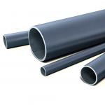
Heating round stove in a metal case

Fig. 107.
The advantages of furnaces in metal cases are that their walls are gas-tight, heat up evenly, begin to give off heat soon after kindling. Furnaces are fairly simple in design and execution. The case usually consists of three sides, which are placed one on top of the other. The heat capacity of a round furnace in a metal case is 1.75 kW. Dimensions: diameter 65 cm, height 229 cm. The fuel burner is intended for burning any type of solid fuel (fig. 107).
Materials Brick - 260 pieces, including fireproof - 65 pieces; ordinary clay - 0.05 m3; refractory clay - 11 kg, sand - 0.03 m3; steel roofing for the case - 6.5 m2; front sheet 50 x 70 cm - 1 piece; roofing sheet or roofing felt for insulation with a diameter of 85 cm - 2 sheets, furnace door 21 x 25 cm - 1 piece, grate 18 x 25 cm - 1 piece; blower door 13 x 14 cm - 1 piece; clean doors 13 x 14 - 2 pieces; View valves 13x13 cm - 2 pieces.


Fig. 108
Order. Prior to commencing work in steel sheets, it is necessary to mark and cut holes for the furnace, blower, cleaning doors and view valves. The construction of the furnace begins with the installation of the first dorsal case on the prepared base. The installation is checked for verticality, the seams between the base and the sill are filled with clay mortar. Then, guided by the planning plan, brickwork is carried out inside the tsargos (Fig. 108).
Frame Furnaces
The main advantage of frame furnaces - small size with increased heat transfer, ease of manufacture, lack of foundation. The heat capacity of frame furnaces is from 1.2 to 3.5 kW. They use any kind of solid fuel.
The frame furnace consists of gratings welded from a steel angle 2.5 x 2.5 x 0.3 cm in size. The kerchiefs are welded to the lower horizontal frame of the frame furnace, and the frontal corner is attached to the front frame to which the furnace and cleaning doors and other metal elements are attached. ovens. Instead of welding, bolting can be used.
At the beginning of the construction of frame furnaces set frame. A metal sheet is placed on the base of the corners, then the lower-level facing sheets are installed and the ash pan, the fuel chamber and chimneys are laid out of the brick. If the furnace is installed on a wooden or other combustible floor, a sheet of asbestos or felt impregnated with clay mortar is placed under its base, and a sheet of roofing steel protruding 10 cm on all sides is placed on top.
After the first section of the frame is laid out, lay out the second section, using the scaffolding. Laying lead on clay solution. Dressing stitches required. Overlapping furnace for sealing covered with clay mortar and revet asbestos cement sheet.
Frame furnaces have a convective smoke system. Flue gases in the ascending channel rise to shut off the stove, consuming heat to heat the upper part of the stove, then descend through the descending canal to shut off the firebox and go down the chimney through the horizontal canal. Flue gases are discharged into the chimney or wall chimney through a metal pipe.
The nadtopny part can be made thin-walled due to the cladding and frame. Frame furnaces can be heated with any kind of solid fuel. To give the furnace an aesthetic look, various ways of facing frame furnaces are used, the simplest of which is painting.
Before painting, heat-resistant EP-0026 putty is applied to the surface of the furnace, which can withstand a temperature range from 150 to 200 ° C. To give the furnace a smooth surface, the putty is polished with emery paper No. 6-8. Putty is applied in three layers. After complete drying of the filler, the surface of the furnace is coated with heat-resistant enamel. The first layer primes the surface. If irregularities are found, they must be sanded. The second layer is applied to a hot, with a temperature of 120-130 ° C, furnace, to obtain a flat surface. Another way of exterior finishing frame furnaces - pasting. First, asbestos cement sheets are applied with epoxy glue. Fiberglass is glued on top of it - a heat-resistant material with high strength and a fairly beautiful appearance. You can revet the oven with ceramic tiles. Ceramic tiles are placed using heat-resistant mastics or metal support structures are made.
Thin-walled frame furnace
Thin-walled frame furnace weighing 300 kg has no foundation. The furnace design does not provide a mounted pipe, it must be connected to a wall chimney or root pipe. The heat output of the furnace is 1.2 kW with two furnaces per day.
MaterialsFor the construction of the furnace you will need: ordinary brick - 64 pieces, including fire-resistant - 16 pieces; ordinary clay - 40 kg; sand - 90 kg; Angle steel with dimensions of 2.5 x 2.5 x 0.3 cm - 10 kg; steel strip 3 x 0.4 cm - 2 kg; asbestos cement sheet 5 mm thick - 2 m2, grate 13 x 13 cm - 1 piece; furnace door 25 x 20.5 cm - 1 piece; sheet steel 1 mm thick - 12 pieces; steel roofing - 7 kg; branch pipe with a latch.
Order.First set the frame. The bottom of the frame is lined with sheet steel and covered with a layer of clay mortar 1 cm thick. 1st row: the front row is laid out with three bricks with spoons towards the front sheet of asbestos-cement lining. In the left rear corner put half a brick, on the left side - tychkovy full brick. Make a continuous laying - the lining. An ash box made of sheet steel with a thickness of 0.8 mm is installed on the first row. 2nd row: six halves of bricks are laid along the perimeter of the ash box. In front lay a hewn brick. Install the grate. On the sides and rear of the grate lay full-dimensional bricks. 3rd row: laid out with refractory bricks. 4th row: on the sides of the furnace door lay bricks bent on the bed. Behind the bricks they install a full-sized hewed brick and two hemmed halves to form a firebox shaft. 5th and 6th rows: in these rows the bricks are stacked on the edge, the laying out of the firebox walls ends. A cast-iron strip 12 cm wide and 38 cm long is laid on top of the bricks of the 6th row. This strip will support the overlapping bricks of the firebox. 7th row: laying out the roof of the firebox. A layer of clay mortar is applied on the floor in order to seal the roof of the firebox. 8th row: the walls of the furnace are laid out of bricks on the edge. In this row, the cleaning is set and the laying of the cutting begins, which forms the descending and ascending channels. 9-12th rows: the formation of the nozzle of the furnace, which increases its storage capacity. 13th row: laying out the stove with six threefolds, laid “on the bed”, resting on the middle bonded brick of the 9th row, sealing it with clay mortar and lining.
There are several designs of frame furnaces, which differ from each other in mass, height, heat emission, and the size of the firebox.
"Swede"This is one of the most convenient heating and cooking stoves, as it has lower heating and a cooker with an extractor hood, relatively small size and high heat transfer. The “Swede”, as well as the Russian stove, was improved over time by stove designers. Below is a description of the masonry of the Shvedka furnace designed by K. Ya. Buslaev. The dimensions of the furnace are 102 x 77 x 201 cm. Heat transfer is 3600 kcal / h.
MaterialsBrick ordinary - 425 pieces; including refractory - 43 pieces; fire door 25 x 20.5 cm - 1 piece; grate 20 x 30 cm - 1 piece; blowing door 14 x 14 cm - 1 piece; door of the cooking chamber 50 x 39 cm - 1 piece; oven 50 x 33 x 28 cm - 1 piece; cast iron two-burner plate 70 x 40 cm - 1 piece; smoke damper 25 x 13 cm; steam latch 13 x 13 cm - 1 piece; front sheet 70 x 50 cm - 1 piece; corner of steel 4.5 x 4.5 x 101 cm - 3 pieces; steel strip 35 x 2.5 x 0.3; 20 x 2.5 x 0.2, 101 x 5 x 0.4; 75 x 5 x 0.4 cm - 4 pieces; cast iron tiles 40 x 25 cm, 40 x 15 cm - 2 pieces.
Order. 1st row: spread on the drawing. You can use halves of bricks. 2nd row: the same as the first, with the obligatory dressing of stitches. Installing the blower door. 3rd row: fix the blowing door. Under the oven make a clean window. 4th row: make the base under the oven. The oven on the side of the firebox is lined with refractory bricks, and on the other three sides it is reinforced with sheets of roofing iron. 5th row: overlap the blowing door and clean the window. In the same row, they put up a grate, lay the base of the firebox with refractory bricks, set up a fire door. 6th row: fix the oven and the furnace door. 7th row: bricks are laid with refractory bricks in the oven. Brick put on the edge. 8th row: spread in order. 9th row: the oven is covered with a layer of clay mortar with a thickness of 0.5-1 cm, the furnace door is covered with a steel strip. A cast-iron stove with burners is installed, reinforcing it with plates of 10-mm steel. From the slab, the clutch is led to the edge. 10th row: begin laying smoke, leaving a window for cleaning. Stove with burners do not lay. 11th row: overlap the first cleaning and make two new ones for cleaning the lowering channels. On the bricks of this series put two steel strips 20-25 cm long - the basis for the hanging walls. 12th row: overlap cleaning of downhole channels. The wire securing the frame of the door of the cooking chamber is fixed at this level. 13th row: put bricks on the edge to arrange the hood-steam collector. 14th row: cover the cooking chamber, leaving a hole for the hood. The 15th and 16th rows: lay out according to the order, leaving space for two stoves. After laying the 16th row, the small stove is covered with a sheet of roofing steel 30 x 28 cm in size. 17th row: they are laid according to the order. 18th row: in the back of a large stove make a clean hole. The inner walls of the first and second channels are not brought to overlap by 20 and 13 cm, respectively. The upper edges of these walls are being cut off. 19th row: masonry is kept flat. This forms a projection of 3 cm. 20th row: overlap the chimney. In this row form another protrusion of 3 cm from the outer part of the furnace. To overlap the stove put a corner on the edge and a steel strip in the middle. The 21st row: the overlap of a large stove and parts of the chimney. A row spread on the size of the 19th row. Here also install smoke and steam valves. 22nd row: they lay out the furnace neck in three rows with a reduction in the cross section of the chimney up to 13 x 26 cm in order to install the second valve. Then lay out a chimney with grooves (Fig. 109).

Fig. 109.
Heating and cooking stove designs I. I. Volkova
The furnace has dimensions of 109 x 89 x 244 cm. Its heat output is 3.9 kW with two furnaces per day. A cooking chamber with an exhaust hood, an oven and a hot-water box are provided in this oven. The furnace can operate in two modes, summer and winter (Fig. 110).

Fig. 110.
MaterialsFor the construction of the furnace will require: brick - 520 pieces, including fireproof - 100 pieces; clay solution - 20 buckets; refractory clay mortar - 50 kg; 18 x 25 cm grate - 1 piece; fire door 21 x 25 cm - 1 piece; blowing, cleaning doors 13 x 13 cm - 5 pieces; door for the cooking chamber with a frame of 38 x 64 cm - 1 piece; cast iron stove with a hob - 2 pieces; cast iron plate 18 x 53 cm - 1 piece; water box 15 x 28 x 57 cm - 1 piece; oven 30 x 28 x 57 cm - 1 piece; 35 x 58 drying rack - 1 piece.
Order. 1st row: lay out solid, leaving room for an ashpit measuring 25 x 13 cm. One brick is being cut off, making the slope toward the ashpit. 2nd row: lay out with bandaging of seams, install the blowing door. 3rd row: to the right of the blower door, the first cleaning door is installed, the blower hole is made already with the help of a hewn brick. 4th row: on the right-hand wall of the oven, a second door is installed, the door of the blower is blocked, and a half brick is placed on the second door, on which the oven will rest. 5th row: masonry is made of refractory bricks, a grate is installed over the ashpit hole, the first cleaning is blocked. 6th row: set the oven and furnace door. 7th row: cover the channel, the side walls of the oven are lined with bricks. 8th row: completely block the channel behind the oven. 9th row: the completion of the lining of the oven from the side of the firebox, the upper brick is released 1-1.5 cm above the oven and cut off. The top of the oven is covered with clay mortar. 10th row: overlap the firebox door and the partition between the oven and the wall of the furnace. 11th row: install cast-iron stoves with burners above the firebox, then a hot-water box and the door of the cooking chamber. The distance between the hot-water box and the cooking chamber is 5-7 cm thick bricks laid on the edge. 12th row: partially overlap the horizontal channel. 13th row: completely block the channel. 14th row: the horizontal channel is lengthened, a back hewn brick is placed behind the hot-water box. 15th row: water heater box overlap. 16th row: move the channel above the hot-water box on the half-brick front, on three sides of the cooking chamber put five pieces of strip steel 12 cm long, 2.5 cm wide and 3 mm thick, the ends should go into the cooking chamber 2 cm. Two pieces the same steel, 15 cm long, is placed under the brick at the back of the furnace. 17th row: lay the grate for drying and set up cleaning above the hot water box. 18th row: shrink channel over cleaning. 19th row: overlap the purge and put a summer bolt. 20th row: put the hood on the right side of the cooking chamber. From the inside put angle steel. 21st row: the top of the cooking chamber is covered with three strips of steel. 22nd row: cover the chamber, exhaust, part of the rear channel. 23rd row: set samovar. 24th and 25th rows: install two cleanings, start laying the upper part of the furnace. 26th row: overlap cleaning and horizontal channel. 27th row: vertical valve is installed. 28th and 29th rows: according to order. 30th row: cover the top of the furnace, leaving one channel. 31st row: installs the last horizontal gate. This is the second row of overlap. 32nd row: third overlap row. 33rd row and beyond: the laying of the chimney.
Design. The dimensions of the furnace in terms of 51 × 89 cm, height 238 cm. It can burn any fuel. The firelighter is located in the lower part of the furnace, its walls are the walls of the furnace itself, which provides the lower heating. Flue gases enter the vertical channel, reflecting from the ceiling.
Material. For the laying of the furnace is required: brick - 355 pieces, including refractory 110 pieces.
Laying the furnace along the rows. 1 row - in front of the bricks lay out butting, the corner bricks break up to 3/4 of the bricks, and the upper faces of the 2 medium boulders, forming a slope inside the masonry to the bottom of the ash pan. The slope is shown in section along the AA. In the back of the row, the space between the outer wall of the furnace and the back wall of the ash pan is covered with dry sand. Backfilling is done up to the 3rd row inclusive.
Fig. 1. Rectangular heating furnace 1 - ashpit; 2 - double door; 3 - fire door; 4 - cleaning; 5 - overlapping; 6 - chimneys; 7 - heat channel; 8-firebox; 9 - grate; 10 - under
2nd row - in the center of the front wall put the blower door. Corner bricks on the right and left of it up to 3/4 bricks, the rest of the masonry from full-sized bricks.
3rd row - after laying the bricks of this row, a steel strip 35 cm long and 4 cm wide is laid over the front part of the ashpit, which is a support for the brick covering the part of the ashpit on the next row.

Fig. 1. Laying heating rectangular furnace
4th row - overlap the front of the ash pan.
In the back of the row, the backfill is bricked up.

Fig. 2. Laying heating rectangular furnace
5th row - they put a grate on the hole above the ashpit. Bricks hemmed in from behind and in front form slopes for coals rolling on the grate.
6th row - put the furnace door in the center of the front wall. The bricks of the back wall are sloped inside and form one inclined plane with the bricks of the previous row. 7th - 12th row - laying of the firebox. The 13th row is the laying of issues for the overlapping of the firebox. The front of the side walls lay out of 3/4 brick.
14th - 15th row - overlap over the firebox. In the back of the left hole connecting the firebox with a vertical channel - Khilo. The 16th row - put the door clean, behind her block "half", laid on the edge. The shelf behind the door is covered with a layer of clay-cement solution to completely isolate the firebox from the smoke channels located above. 17th - 20th row - laying of vertical smoke channels.
The 21st - 22nd row - connects the lifting smoke channel coming from the firebox with the downstream channel. Here, the gases from the firebox roll over through a cut, which separates the channels, into the middle lowering channel, through which they reach the 18th row, and get through the roll-through into the front lifting channel. 23rd - 24th row - overlap the middle and rear channels.
25th - 26th row - put a door to clean the bottom of the chimney, resulting in a spin from the middle channel of the second tier to the chimney. 27th - 30th row - laying of smoke channels of the second tier, of which the back is the beginning of the chimney.
On the 28th row they put the first view valve. On the 30th row complete the second cycle of revolutions. Here, the flue gases from the front elevation channel pass into the middle lowering channel and, after descending along it to the undercut, on the 26th row enter the chimney.
31st row - lay out the issues for shutting off the stove. 32nd - 34th row - overlapping furnace. Bricks are laid so that all vertical joints of the first row are blocked.
On the 32nd row put the 2nd latch valve. The installation of 2 swing valves reduces the heat loss of the furnace. In the absence of valves, a round view is put on the 32nd row. 35th row and the subsequent - laying chimney.
Heating rectangular stove
Related articles